Section 4: Using the Model 9500B — DC/Square Function 4.5-3
Final Width = 215mm
Descriptions assume 9500B/1100
4.5.3.9 DC/Square Selection
Summary
'DC' and 'Square' can be regarded as a combined
dual function, as each has a similar purpose,
and switching between the two is accomplished
by selection in a common 'Waveform' menu.
The parametric differences are evident once
the appropriate waveform soft key has been
pressed.
Detailed operation follows below:
paras 4.5.4 (DC/Square Operation)
paras 4.5.5/6 (Square Operation)
paras 4.5.7/8 (DC Operation).
4.5.3.8 DC Selection
Pressing one of the two DC keys, for example:
the
(DC Negative) key, will return to the
previous screen, with the DC Negative icon
showing in the top left corner. The parameters
listed on the screen will be changed to reflect
DC instead of Square:
Pressing first the required ratio, then 'EXIT'
returns to the trigger selection screen. On this
screen, no indication of the trigger ratio is
given.
Note: Beware that a low frequency sub-
divided in this way could lead to a very
long delay before a trigger occurs.
Note that the expected load key in the bottom
right corner is now de-activated, and the trigger
state legend in the top central box is fixed on
50Ω. A further selection is available, to choose
the trigger ratio.
4.5.3.5 Trigger Ratio
The 'Trigger Ratio' is the ratio of the trigger
frequency to the that of the waveform itself.
Three ratios are available: '÷1', '÷10' and '÷100'.
Pressing the 'TRIGGER RATIO' key presents
the following screen:
TODAY'S DATE TIME
OFF
SIGNAL CH1 5ØΩ
TRIGGER NONE
5.ØØ mV/div x4 = 2Ø.ØØØ mV
pk-pk
Deviation
= ØØ.ØØ %
O/P
Amplitude
= 2Ø.ØØØ mV
pk-pk
Frequency
= 1.ØØØØ kHz
WAVE
FORM
1
2
5
1.Ø
CHANNEL
SELECT
TODAY'S DATE TIME
OFF
SIGNAL CH1 5ØΩ
TRIGGER CH5 5ØΩ
O/P
Amplitude
= 2Ø.ØØØ mV
pk-pk
Frequency
= 1.ØØØØ kHz
TRIGGER
CH 2
CHANNEL 1
>
9530 1.1Ghz 150ps
CHANNEL 2
>
9530 1.1GHz 150ps
CHANNEL 3
>
9510 1.1GHz 500ps
CHANNEL 4
>
No Head
CHANNEL 5
>
Trigger Cable
TRIGGER
CH 4
TRIGGER
CH 1
EXIT
SIGNAL
CHANNEL
TRIGGER
RATIO
CABLE
SELECT
TRIGGER
NONE
TRIGGER
CH 3
TRIGGER
CH 5
TODAY'S DATE TIME
OFF
SIGNAL CH1 5ØΩ
TRIGGER CH5 5ØΩ
O/P
Amplitude
= 2Ø.ØØØ mV
pk-pk
Frequency
= 1.ØØØØ kHz
CHANNEL 1
>
9530 1.1Ghz 150ps
CHANNEL 2
>
9530 1.1GHz 150ps
CHANNEL 3
>
9510 1.1GHz 500ps
CHANNEL 4
>
No Head
CHANNEL 5
>
Trigger Cable
EXIT
÷ 1Ø
÷ 1ØØ
÷ 1
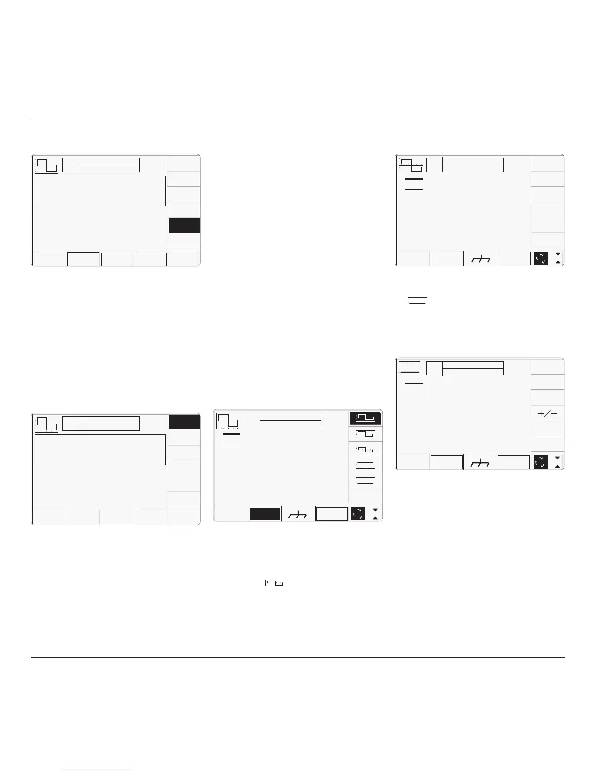
The WAVEFORM key label is highlighted to
indicate that waveform selection is available,
as is the presently-selected waveform icon.
Pressing one of the waveform keys (for
example: the
key) to select a different
waveform will return to the previous screen,
with the icon of the selected waveform showing
in the top left corner:
TODAY'S DATE TIME
OFF
SIGNAL CH1 5ØΩ
TRIGGER NONE
x 1Ø
÷ 1Ø
∆ = Ø
5.ØØ mV/div x4 = 2Ø.ØØØ mV
Deviation
= ØØ.ØØ %
O/P
Amplitude
= -2Ø.ØØØ mV
WAVE
FORM
CHANNEL
SELECT
1
2
5
1.Ø
TODAY'S DATE TIME
OFF
SIGNAL CH1 5ØΩ
TRIGGER NONE
x 1Ø
÷ 1Ø
∆ = Ø
5.ØØ mV/div x4 = 2Ø.ØØØ mV
pk-pk
Deviation
= ØØ.ØØ %
O/P
Amplitude
= 2Ø.ØØØ mV
pk-pk
Frequency
= 1.ØØØØ kHz
1
2
5
1.Ø
WAVE
FORM
CHANNEL
SELECT
4.5.3.6 Retained Channel Memory
All selections made for Signal Channel, Trigger
Channel, Cable Select and Trigger Ratio are
retained in non-volatile memory within the
9500B. Changing modes and functions; and
powering the instrument on and off will not
alter these selections.
For this reason, there are no true defaults for
these parameters, although on receipt from
manufacture you should find the following
selections are already made:
Signal Channel:
1
Trigger Channel:
NONE
Cable Select:
Not selected
Trigger Ratio: ÷
1
4.5.3.7 Choosing a Waveshape
All waveshapes in this function can be selected
on a second menu screen. This is activated by
pressing the '
WAVEFORM
' screen key on the
bottom row. The screen changes to show the
available waveforms: