Section 7: Model 9500B — Specifications 7-9
Final Width = 215mm
Reference Frequency Input (BNC) Output (BNC)
Frequency Range: 1MHz to 20MHz 1MHz or 10MHz
in 1MHz steps
Level: (typical) 90mV - 1V pk-pk Into 50Ω : 1V pk-pk
Into 1MΩ: 2V pk-pk
Lock Range: ±50ppm
7.9.8 Reference Frequency
Auxiliary Input
Signal Routing: Rear SMA input,
passive and switched 50Ω path
to any Active Head
Maximum Input: ±40V pk-pk, ±400mA pk-pk
Switching Break ±5V pk-pk, ±100mA pk-pk
and Make Capacity
VSWR <1.2:1 typ to 1.1GHz
Insertion Loss to 100MHz <2.5dB,
(Into 50Ω) to 500MHz <4dB,
to 1GHz <6dB
7.9.7 Auxiliary Input
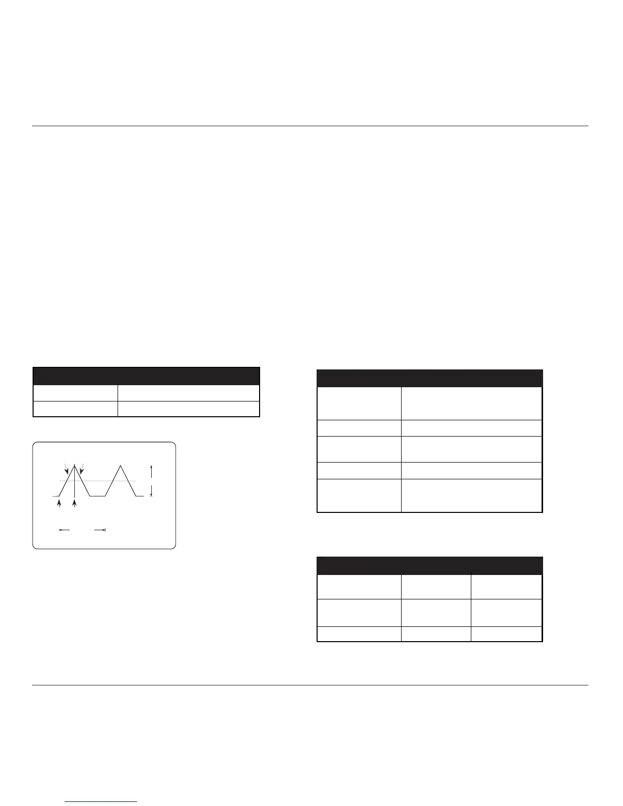
0V
Rising
Ramp
Falling
Ramp
period
Flat
+
-
1Vp-p
Alternative
Triggers
LF Linear Ramp — Waveshape
Input Leakage Function
Open Circuit Output Leakage < ±50pA
Short Circuit Output Offset < ±15µV
7.9.6 Input Leakage