Section 4: Using the Model 9500B — Interconnections 4.2-1
Final Width = 215mm
Descriptions assume 9500B/1100
4.2 Interconnections
4.2.1 Introduction
This sub-section deals with the Active Head
Technology™ used to connect the 9500B to a
UUT oscilloscope, and rear-panel signal inputs
and outputs. Section 4.2 is divided into the
following sub-sections:
page
4.2.1 Introduction 4.2-1
4.2.2 Active Head Technology ™ 4.2-1
4.2.2.1 Connections to the 9500B
and UUT Oscilloscope .................................... 4.2-1
4.2.2.2 Head Module Signal Processing .................... 4.2-1
4.2.3 AUX IN (Rear Panel) 4.2-2
4.2.4 REF FREQUENCY INPUT 4.2-2
4.2.5 REF FREQUENCY OUTPUT 4.2-2
4.2.6 Single and Multiple Channel Outputs 4.2-2
4.2.6.1 Single-Channel Variants ................................. 4.2-2
4.2.6.2 Option 5 ......................................................... 4.2-2
4.2.2 Active Head Technology
The main function of a head is to route the
9500B's output to the UUT oscilloscope input
channel without intervening cables that could
degrade the signal.
Each head contains output circuitry that
generates and supports the transmission of
pulses of very short rise and fall times with low
distortion, and amplitude variable from ±5mV
to ±3V, and good 50Ω matching. This is
achieved by the use of low-loss substrate
dielectrics, with wide-band components,
attenuators and relays. The heads also perform
the function of sinewave levelling.
Available head modules include:
• Model 9510 — 1.1GHz Output Module
with 500ps pulse edge capability.
• Model 9530 — 3.2GHz Output Module
with 150ps and 500ps pulse edge capability.
• Model 9550 — Output Module with 25ps
pulse edge capability only.
• Model 9560 — 6.4GHz Output Module
with 70ps pulse edge capability.
Electrical specifications apart, modules are
interchangeable. The 9500B accepts any mix
of types, up to five modules.
4.2.2.1 Connections to the 9500B
and UUT Oscilloscope
Two connections are used for each head. An
18-way connector and cable provides power
supplies, control and sense signals, whereas a
separate coaxial connector and cable carries
the signal or clock. The output signal is
delivered directly to the UUT oscilloscope's
input channel through the single BNC or
PC3.5 connection.
Caution:
The
!
symbol, shown on the 9500B front
panel and heads, draws attention to information
contained in this handbook regarding maximum
output voltages and currents.
For details, refer to Section 7: Specifications.
4.2.2.2 Head Signal Processing
Signal processing in the head modules can be
summarized by considering the 9500B
functions:
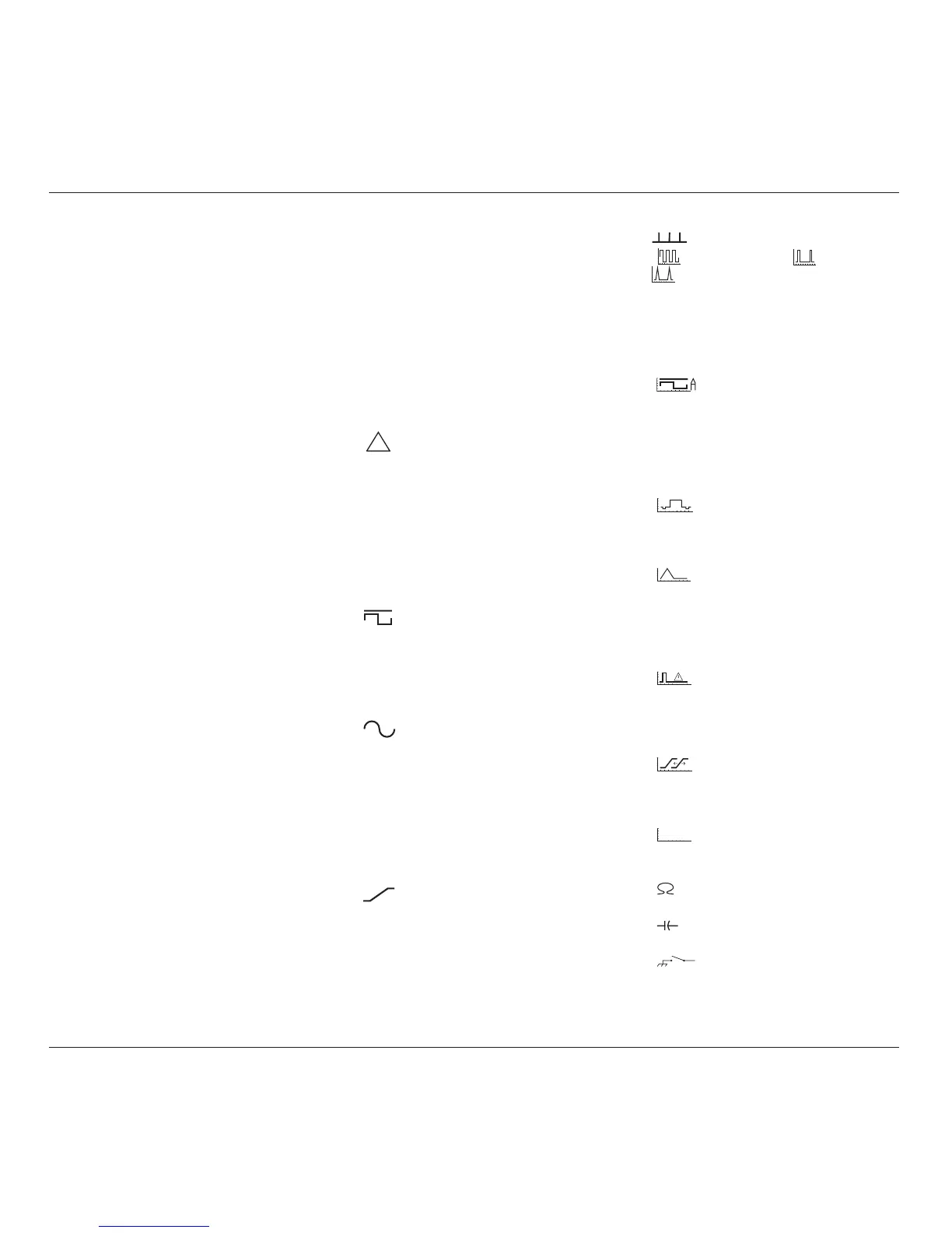
a.
DC/Square . The signal is routed
directly via switched attenuators to the
output BNC or PC3.5 socket. Sensing
from the output is passed back to the
mainframe, effectively providing a 4-wire
delivery.
b.
Sine. The sinewave at its final
frequency is passed through the input SMA
coaxial cable. Sinewave amplitude is set
in the mainframe, but sensing for sinewave
levelling takes place in the head itself,
returning the levelling control signal to the
mainframe. The levelled signal is routed
via attenuators to the output BNC or PC3.5
socket.
c.
Edge. Pulse levels and timing
originate in the mainframe and pass to the
head for control of the edge generating
circuitry. Pulses with 500ps edge are routed
via the LF/DC attenuators to the output
BNC or PC3.5 socket (Models 9510/9530).
Special attenuators in Model 9530/9560
are used for the 150ps or 70ps edge pulses.
d.
Markers. Marker types:
(
Square/Sine, Pulses or
Narrow Triangle waveform), timing
and levels originate in the mainframe and
pass directly via switched attenuators to
the output BNC or PC3.5 socket. Line
frequency markers are also included.
e. Aux.
i.
DC/Square Current Source.
Current outputs between 100µA and
100mA are derived from the DC/Square
voltage source via an external BNC current
loop accessory (50Ω load to 9500B
output).
The output calibrates current probes.
NB. Not compatible with 9550 or 9560.
ii.
Composite Video. Video voltage
outputs are passed directly via the output
BNC or PC3.5 to test TV sync separator
functions.
iii.
Linear Ramp. Symmetrical
triangular 1Vp-p waveforms of period
3ms to 3s are passed via the DC/Square
voltage route to the output BNC or PC3.5.
These calibrate trigger level markers and
check DSOs for missing ADC codes.
iv.
Overload Pulse. High energy
pulses between 5V and 20V of limited
duration are passed via the DC/Square
voltage route to the output BNC or PC3.5,
to test 50Ω terminator protection.
v.
Zero Skew. Permits 9500B
channels/heads transit times to be
harmonized, in order to test UUT input
channel trigger synchronization.
vi.
AUX IN
AUX IN. Routes external
calibration waveforms to an active head's
BNC or PC3.5 output.
vii.
Load Resistance. Measures load
resistance in the active head's output circuit.
viii. Load Capacitance. Measures load
capacitance in the active head's output circuit.
ix.
UUT Input Leakage Tests. Short/
Open-circuit outputs directly to the output
BNC or PC3.5 allow testing of
oscilloscope input leakage current.
continued overleaf
→