Revision 14
19 August 02, 2019
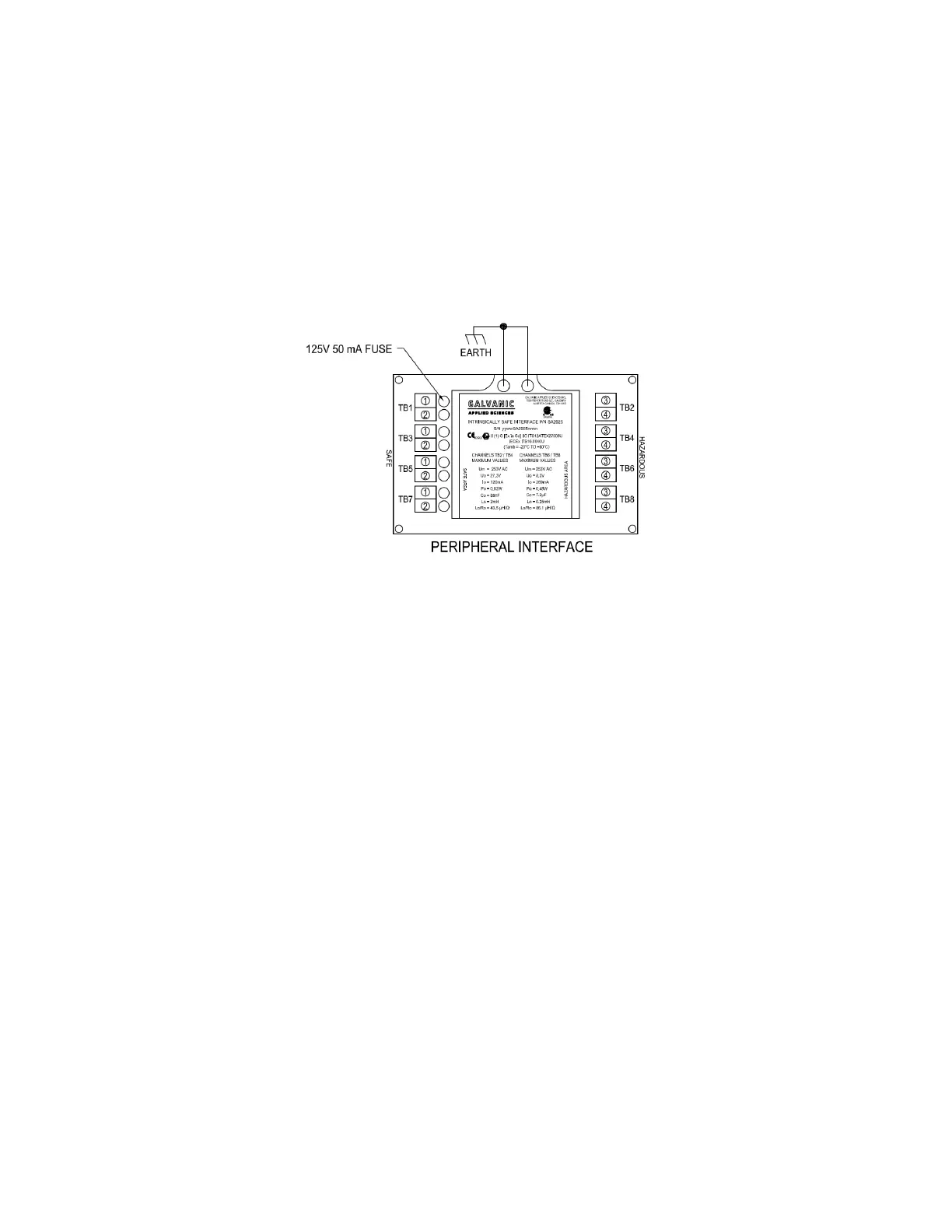
2.3 Intrinsically Safe Barrier Board (Peripheral Interface)
For Class 1, Division 1 systems, all electrical connections between the electronics enclosure
and the chassis must pass through an intrinsically safe barrier. The intrinsically safe barrier
connections are shown in Figure 2-2. Class 1, Division 2 analyzers do not employ an
intrinsically safe barrier.
Figure 2-2: Intrinsically Safe Barrier (Peripheral Interface) Connections
There are several connections that must pass through the barrier. The connections on the left
side of Figure 2-2 are on the hazardous side and come from the chassis. The connections on
the right of the figure are on the safe side. These connections are used for the keypad wiring,
power to both the sensor block and the Optical Encoder, and signal wiring to carry
communications between the sensor block and the electronics assembly.
2.4 LCD Display Board, Keypad and LED’s
2.4.1 User Interaction Features
The system presents the system status to the operator via a 128 x 64 LCD display on the
front panel. In addition, there are ten LED indicators which provide information about the
status of the system.
A hand held keypad is used to communicate with the system. Operation of the system via the
keypad is described in Section 4.
A detailed application program for a personal computer is provided to monitor the system,
view archived data and establish input and output protocols from/to external devices. A
detailed discussion of the user interface is presented in Chapter 5.