Revision 14
74 August 02, 2019
5.2.2.2 Operation Toolbar
The Operation toolbar contains several buttons that control various aspects of the operation
of the analyzer and the GUI. Table 5-2 shows the buttons in the Operation toolbar.
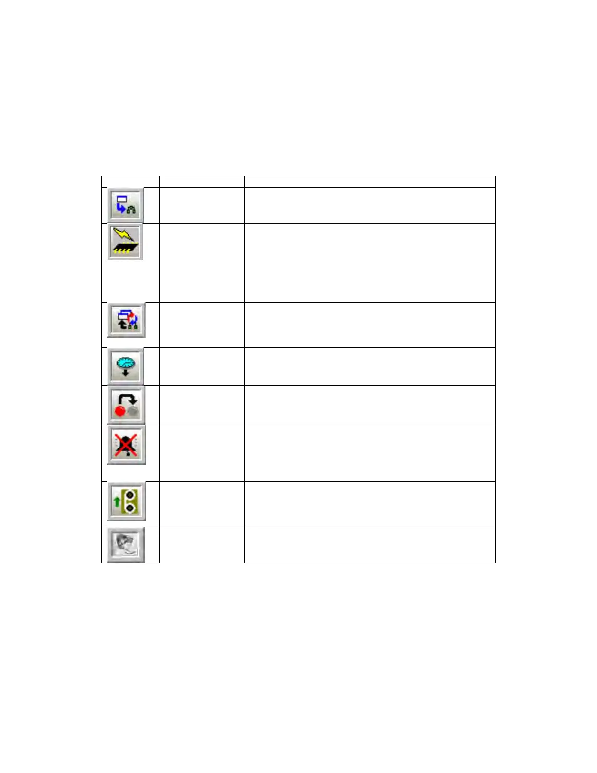
Table 5-2: Operation Toolbar Buttons
to Analyzer
Writes any configuration changes in the active screen
to the analyzer’s volatile memory.
Permanent Write
Configuration to
Analyzer
Writes any configuration changes in the GUI first to the
volatile memory and then writes the changes to non-
volatile flash memory. Any changes that the user
wishes to be permanent and to be present if the
analyzer is powered off must be written to flash. If the
analyzer is powered down before changes are written
to flash, those changes will be lost.
Reads back all the data points on the current screen.
Pushing this button allows the user to check and
ensure that any changes written to the analyzer have
Time
Updates the on-board real time clock in the analyzer to
the time and date set on the linked computer.
Latches
Returns all latches that may have been triggered by
alarms to their default configuration.
Puts the analyzer into bypass mode, where events
associated with alarms (relays, solenoids, etc) are
ignored. When this button is depressed, the bypass
mode is enabled. When the bu
tton is not depressed,
bypass mode is disabled.
Instructs the analyzer to run the motor to advance the
tape and perform a calibration of the sensor block.
Pressing this button is the equivalent of cycling the
power to the analyzer.
Firmware
Updates the analyzer with the latest firmware. This is
done offline but the user must ensure that the correct
communications port has been selected.