Revision 14
33 August 02, 2019
Section 3 Installation
3.1 Receiving the System
When the system arrives, inspect the packaging for external signs of damage. If there is any
obvious physical damage, contact the shipping agent and Galvanic Applied Sciences to
report the damage and request that the carrier's agent be present when the unit is unpacked.
It is recommended that you retain the shipping container so that it may be used for future
shipment of the unit, if necessary.
3.2 Installation Requirements
3.2.1 Electrical Requirements
The system can be powered by 100-230 VAC or 10-32 VDC sources. The power requirement
is 10 W.
If desired, it is possible to connect both AC and DC power supplies. In this manner, the DC
power supply as a backup power. When choosing a power source, the type of solenoid
drivers need to be considered (AC or DC).
The total sulfur option requires 250 W at 120 VAC or 230 VAC.
3.2.2 Location of the System
The system is designed to be operated at ambient temperatures from 10 - 50
o
C. Galvanic
offers complete analyzer shelters from sun shades to complete building, please contact
Galvanic Applied Sciences, Inc. (or your local representative) for additional information.
The system should be mounted in a location where it is not exposed to excessive vibration.
In addition, it should be mounted in a location where the ambient pressure remains relatively
consistent over the course of a day
The vent line cannot have any backpressure on it, as backpressure can seriously impact
readings. The vent line should be as short as possible at a slight continuous downward slope.
3.2.3 Space Requirements
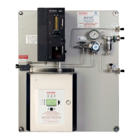
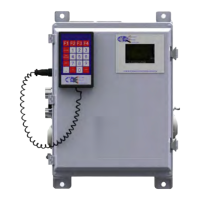
The system dimensions are provided in Figure 3-1 for Class I systems and Figure 3-2 for
Class I Division 1 systems with the total Sulfur option. For Class I Division 2 systems, the
corresponding figures are presented in Figures 3-3 and 3-4