Concord 4
Installation Manual
24
Connecting exterior/interior piezo sirens
Onboard output 1 (OUT 1—terminal 9) is a 9 to 14 VDC switched, programmable output that can handle a
maximum of 1,000 mA current. The default setting (01614) activates the output 30 seconds after a police or
fire alarm condition occurs. This allows you to connect a piezo siren without changing the output configuration
number in programming. This output is typically for exterior siren applications. (For more information on
output configuration numbers, see Onboard options menu on page 99.)
Note: For 24-hour backup, external power drain is limited to 90 mA (during normal standby condition), using a 4.5 or 5.0 Ah
battery, or 190 mA continuous using a 7.0 Ah battery.
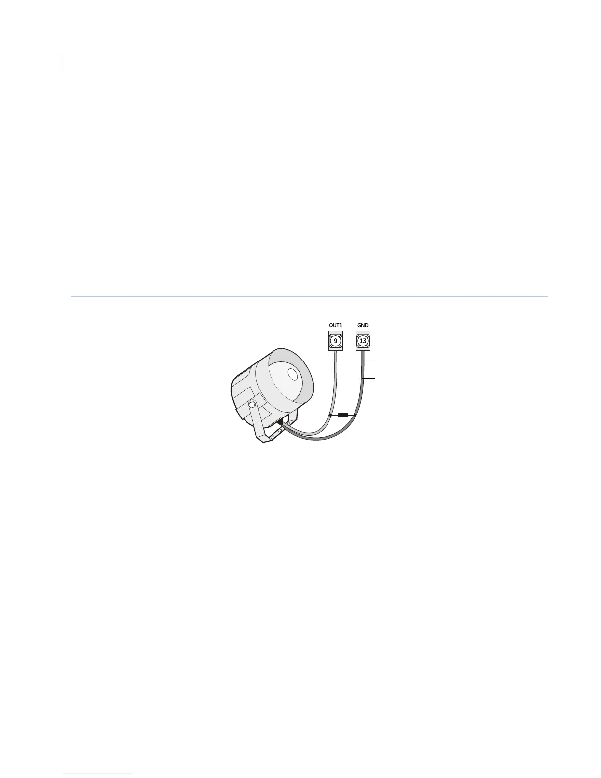
Piezo dynamic exterior siren (13-950)
This siren is not UL listed for use as an outdoor sounding device. Connect the siren to panel as shown in
Figure 11.
Figure 11. Connecting exterior sirens
Output 2
Onboard output 2 (OUT 2—terminal 10) is an open-collector (switched path-to-ground), programmable output
that can handle a maximum of 300 mA current sink and up to 14 VDC. The default setting (01710) activates
the output for status and alarm tones, allowing for a piezo siren connection without changing the output
configuration number. This output is typically used for interior siren applications. (For more information on
output configuration numbers, see Onboard options menu on page 99.)
Hardwired interior siren (13-949)
This siren has two inputs; steady (#1) and warble (#2). Use the steady (#1) terminal for Concord 4 panels. The
siren also includes a cover tamper switch that can be connected to a hardwired zone input on the panel,
SnapCard or SuperBus 2000 hardwired input module. Connect the siren to the panel/zone input terminals as
shown in Figure 12 on page 25.
Black
Panel terminals
Red

 Loading...


