Concord 4
Installation Manual
34
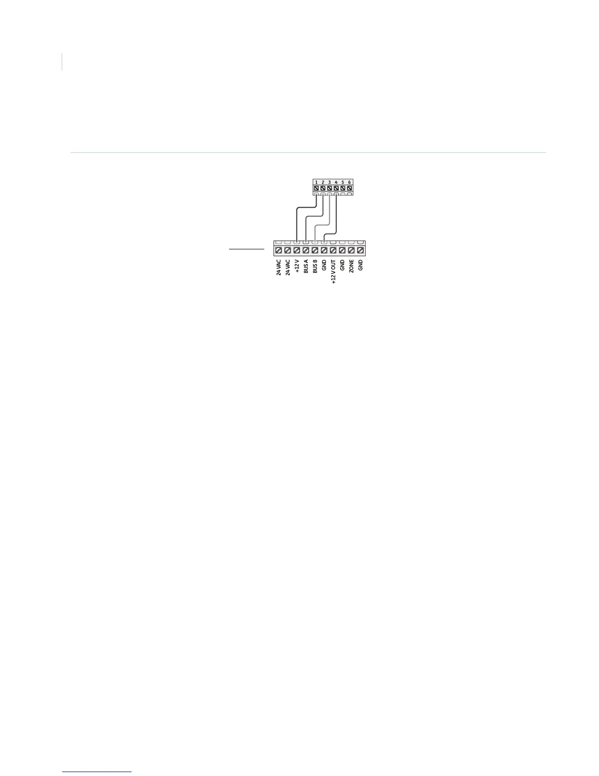
SuperBus 2000 wireless gateway-ready kit
Connect the SuperBus 2000 wireless gateway module to the SuperBus 2000 terminals as shown in Figure 25.
Figure 25. Connecting a wireless gateway module to the panel
The panel cannot be used on a digital or PBX phone line. These systems are designed for digital type devices
only, operating anywhere from 5 VDC and up. The panel uses an analog modem and does not have a digital
converter, adapter, or interface to operate through such systems.
RJ31X phone jack
Use the following guidelines when installing an RJ31X phone jack for system control by phone and central
station monitoring:
• Locate the RJ31X jack (CA-38A in Canada) no further than five feet from the panel.
• The panel must be connected to a standard analog (loop-start) phone line, that provides 48 VDC (on-
hook or idle).
• For full line seizure, install an RJ31X phone jack on the premises phone line so the panel is ahead of
all phones and other devices on the line. This allows the panel to take control of the phone line when
an alarm occurs, even if the phone is in use or off-hook.
Note: Connecting the panel to an analog line off the phone switch places the panel ahead of the phone system, preventing
panel access from phones on the premises. However, the panel can still be accessed from offsite phones.
• If an analog line is not available, contact a telecommunication specialist and request an analog line off
the phone switch (PBX mainframe) or a 1FB (standard business line).
To connect a phone line to the panel using an RJ31X/CA-38A jack, see Figure 26 on page 35, and do the
following:
1. Run a four-conductor cable from the TELCO protector block to the jack location.
2. Connect one end of the cable to the jack.
3. At the TELCO protector block, remove the premises phone lines from the block and splice them to the
black and white (or yellow) wires of the 4-conductor cable.
4. Connect the green and red wires from the 4-conductor cable to the TIP (+) and RING (-) posts on the
block.
SuperBus 2000 2-amp
power supply terminals

 Loading...


