Chapter 2
Installation
27
Figure 15. Installing SuperBus 2000 modules
SuperBus 2000 2-amp power supply (600-1019)
Refer to the power supply documentation for the mounting procedure.
Note: Do not connect power (AC and battery) to the power supply until the panel is ready for power-up. For power supply AC
and battery connections, see the SuperBus 2000 2 Amp Power Supply Installation Instructions.
Connect the power supply to the panel terminals and devices to be powered as shown in Figure 16.
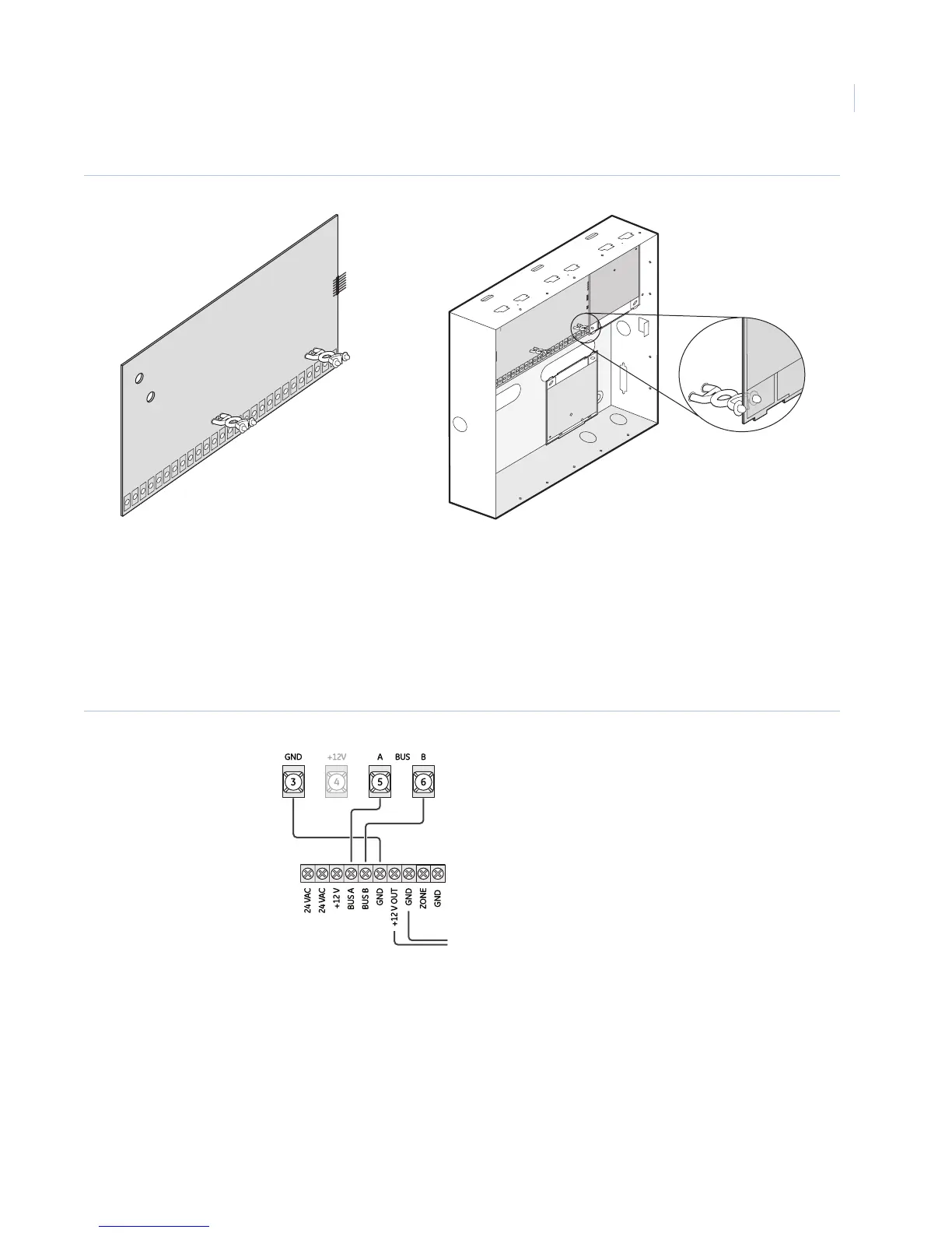
Figure 16. Wiring the SuperBus 2-amp power supply to the panel
SuperBus 2000 transceiver module and SuperBus 2000 RF receiver module
The transceiver and receiver expand RF reception range when placed in the vicinity of sensors on the fringe of
panel RF reception. Refer to transceiver or receiver documentation for mounting information.
Connect the transceiver and receiver (up to four total) to the panel as shown in Figure 17 on page 28.
Note: When installing SuperBus 2000 RF receiver modules, the antenna tamper feature must be set to off (See Reporting -
global settings on page 73).
Support
Standoffs
Top
Mounting
Clips (6)
Side
Mounting
Clip
Screws
Panel terminals
To power inputs on devices
Power supply terminals
 Loading...


