Centralized audio applications
4.6 EST3 Installation and Service Manual
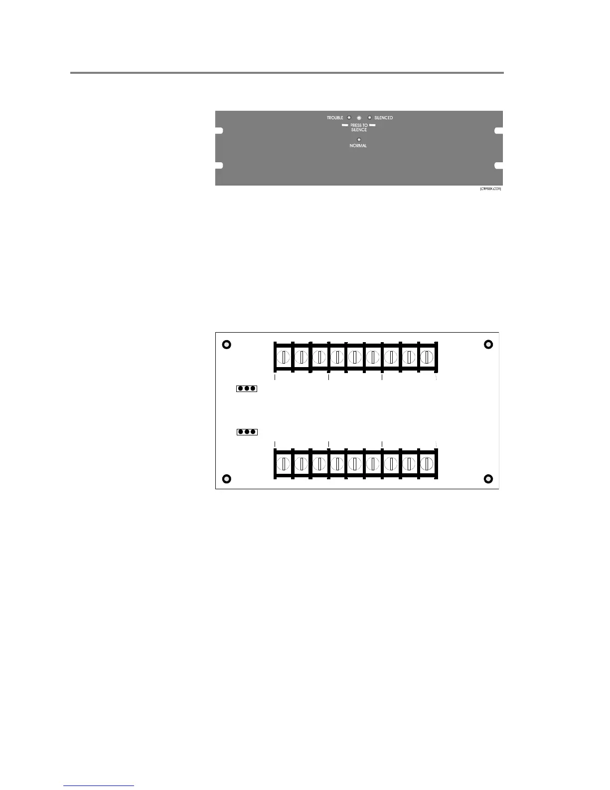
ATP Amplifier Terminal Panel
Figure 4-2: 3-ATP, front view
The Amplifier Terminal Panel, is a 5-1/4 inches (13.34 cm) high x
19 inches (48.3 cm) wide unit that senses loss of AC power or
brownout conditions affecting the amplifiers. It also provides
battery backup to the amplifiers if the audio system is active when
the power failure or brownout occurs. The ATP must have a 3-
ATPINT interface Card installed in order to work with the EST3
system.
[3atpint3.cd
]
IN
IN
P1
PREAMP 1
70V 25V
PREAMP 2
70V 25V
1
1
P2
OUT RISER
OUT RISER
OUT PRE-AMP
OUT PRE-AMP
PRE-AMP 1
PRE-AMP 2
+ - S + - S + - S
+ - S + - S + - S
Figure 4-3: 3-ATPINT Interface Card
The ATP with 3-ATPINT installed, is mounted in an RKU rack
and provides termination for the power amplifier’s audio power
and control signals. The panel has an integral battery charger
capable of charging a maximum of 40 Ah sealed, lead-acid
batteries. The charger is fully supervised and provides a
silenceable trouble buzzer and trouble contacts. One ATP is
required for every two amplifiers.
When a brownout condition is sensed at the ATP, the trouble
contacts and AC fail contacts are closed, and an EST3 supervisory
zone reports the condition to the EST3 system. The EST3 system
is designed to provide +24 Vdc to the ATP’s audio activity input
via control relay, enabling backup power only when both primary
A 3-ATPINT Interface must
be installed on the ATP
when used with the EST3
system.