Installation
EST3 Installation and Service Manual
5.24
Local rail module installation
Please refer to the installation sheet that came with the product
for installation instructions.
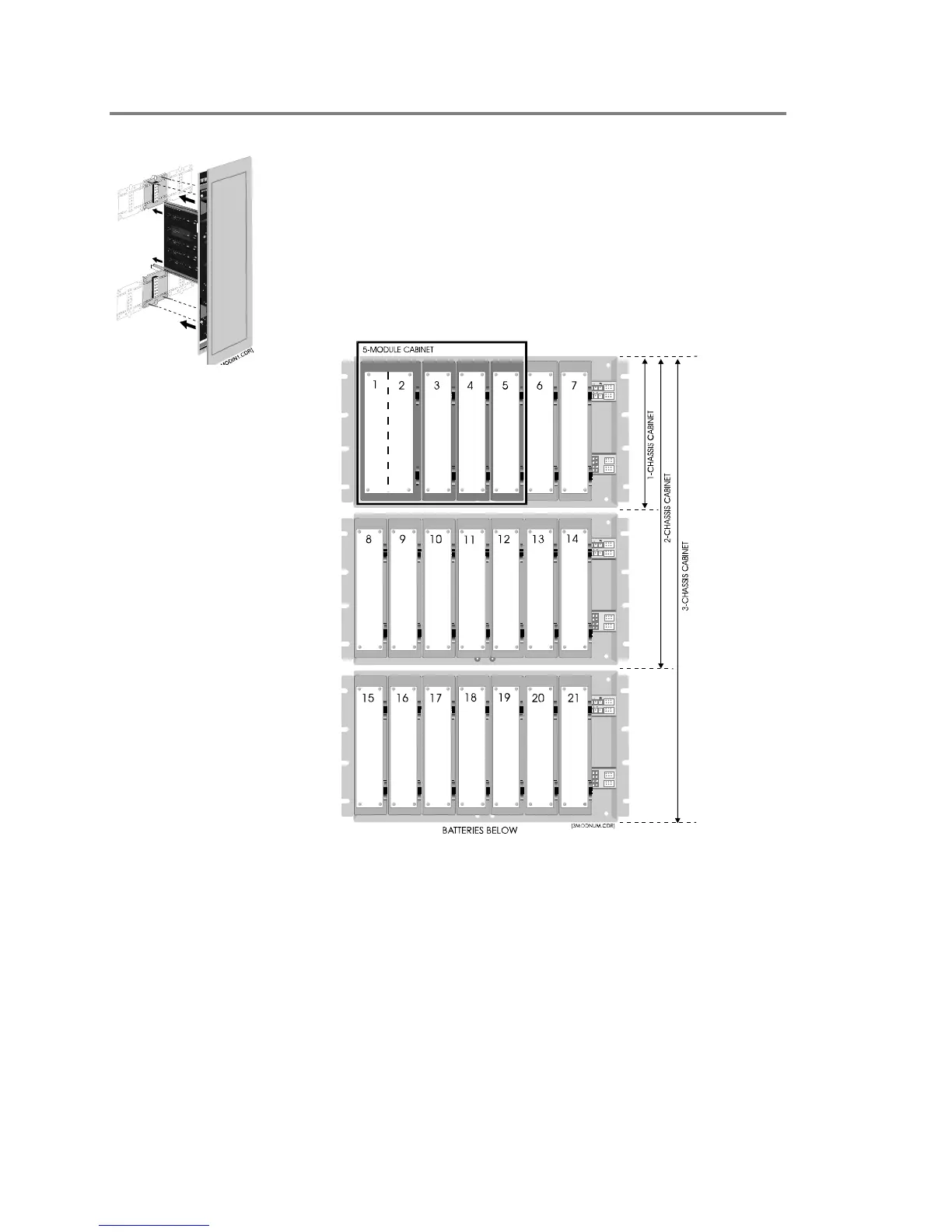
Equipment locations within a chassis are referred to as rail slots.
Figure 5-7 indicates the rail slot numbers for the various cabinet
sizes available in the EST3 product line. The CPU module must
always occupy rail slots 1 and 2. The primary power supply
monitor module should occupy rail slot 3.
Figure 5-7: Local rail module slot identification
A 3-ASU Audio Source Unit occupies the first three slots on its
chassis, and is identified using the lowest slot number of the
three. When a Firefighters Telephone Control Unit is supplied as
part of the 3-ASU/FT, the telephone control unit occupies the
last four slots on the chassis, and is identified as the fourth slot
number (11 or 18) on the chassis.
Connect the DC power cable (P/N 250187) to connector P2 on
the power supply. For the 3-PPS Primary Power Supply, connect
the 16-pin data ribbon cable (P/N 250188); (Booster = P/N
250189) to connector P3 on the power supply. For 3-BPS