Listing requirements
EST3 Installation and Service Manual C.3
Minimum requirements for UL security applications
Local mercantile premises
Standard: UL 609
Minimum hardware:
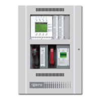
• 3-RCC7 Remote Closet Cabinet
• ATCK Attack Kit
• 3-TAMPRCC Cabinet Tamper Switch
• Central Processor Unit (CPU)
• 3-PPS/M Primary Power Supply
• Main LCD Display (LCD)
—or—
KPDISP Keypad Display
• 3-SAC Security Access Module
• Signature Controller Module
• Listed bell and bell housing: Ademco model AB12M Bell in
Box
• 24DC12 12 Vdc Voltage Regulator with Security Bell
Interface
• 3-IDC8/4 Traditional Zone I/O Module
• SIGA-MD Motion Detector
• SIGA-SEC2 Security Loop Module
Additional requirements:
• Standby power must provide 24 hours of standby with 15
minutes of alarm
• Maximum entry or exit delay must be 60 seconds
• Bell test must be included in system programming, if not a
built-in feature of the software
• System must be programmed for a minimum of 15 minutes
bell ring on alarm
• System must be programmed to indicate bell timeout with an
LED
• System power supply, bell power supply (24DC12), and bell
monitoring module (IDC8/4), must all be inside the ATCK
Attack Kit protected cabinet
Police station connection using a 3-MODCOM or
FireWorks
Standard: UL 365
Minimum hardware:
• 3-RCC7 Remote Closet Cabinet
• ATCK Attack Kit
• 3-TAMPRCC Cabinet Tamper Switch

 Loading...