Installation
EST3 Installation and Service Manual 5.53
Connecting an external modem for use with the Remote
Diagnostics Utility
Using the Remote Diagnostics Utility requires that you connect
an external modem to a CPU equipped with a 3-RS232 option
card.
Some applications may require that the modem be permanently
mounted. The following is a suggested method for mounting a
modem connected to the CPU. First you will need to obtain the
following parts
• MFCA accessory enclosure
• SIGA-MP1 mounting plate
• 2 cable ties long enough to go around the modem and
through the slots on the SIGA-MP1
To mount the modem:
1. Mount the MFCA enclosure back box at an acceptable
location within reach of the panel. Refer to Figure 5-12.
2. Secure the modem to the SIGA-MP1 with the 2 cable ties.
3. Screw the SIGA-MP1 to the MFCA enclosure back box.
4. Connect all modem wiring. Refer to the technical
documentation that came with the modem for wiring
connections.
RS-232 wiring must maintain a 1/4-in minimum separation
between nonpower-limited wiring.
5. Screw the MFCA cover to the back box.
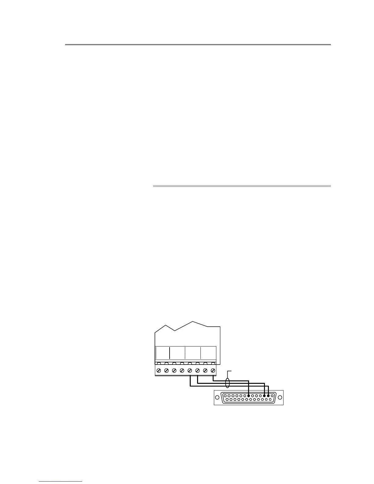
6. Attach the modem RS-232 wires to the CPU serial port
terminals. The serial port must be configured for Remote
Diagnostics in the project database. See below.
CPU
TB2
R
X
111
T
X
R
T
S
2122
C
X
O
M
R
R
T
X
T
S
2
C
O
M
DB-25 male connector (rear view)
to modem RS-232 connector
Modem serial cable