EST3 Installation and Service Manual 6.1
Chapter 6
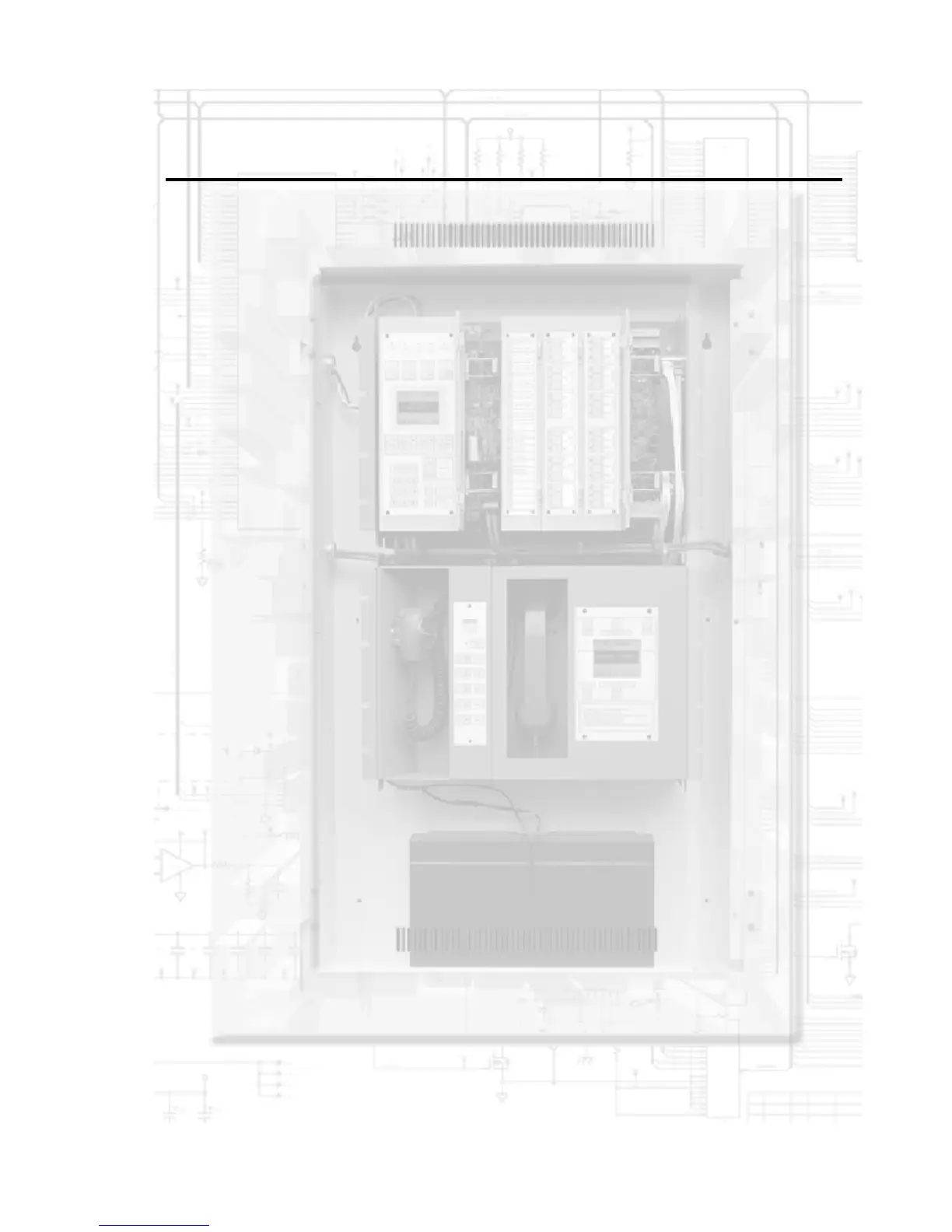
Power-up and testing
Summary
This chapter provides information and procedures necessary to
perform initial system power-up and acceptance testing.
Content
Cabinet power-up procedure • 6.3
Initial power-up • 6.3
Runtime and system errors • 6.4
Introduction • 6.4
Runtime errors • 6.4
System errors • 6.5
Initial and reacceptance test procedures • 6.6
Introduction • 6.6
Control and emergency communications equipment testing • 6.7
Primary power supplies • 6.7
Booster power supplies • 6.7
CPU with LCD module • 6.8
3-RS232 card installed in CPU • 6.10
3-RS485 card installed in CPU, Class B configuration • 6.10
3-RS485 card installed in CPU, Class A configuration • 6.11
3-IDC8/4 Initiating Device Circuit module • 6.11
3-SSDC(1) Signature Driver Controller module • 6.11
3-AADC(1) Addressable Analog Driver Controller
module • 6.12
3-OPS Off-premises Signaling module • 6.12
3-ASU Audio Source Unit • 6.14
3-FTCU Firefighter Telephone Unit • 6.14
3-ZAxx Audio Amplifiers • 6.16
Control/display modules • 6.16
Amplifier transfer panel (ATP) • 6.17
Detector, input module, and output module testing • 6.18
Signature Series detectors and bases on a 3-SSDC(1)
module circuit • 6.18
Addressable analog detectors on a 3-AADC(1) Module
circuit • 6.19
Traditional 2-wire smoke detectors connected to 3-IDC8/4
modules • 6.19
Conventional 2-wire smoke detectors connected to SIGA-
UM modules • 6.19
Signature series input modules • 6.20
Signature series output modules • 6.20
Initiating device testing • 6.21
Manual stations • 6.21
Nonrestorable heat detectors • 6.21
Restorable heat detectors • 6.21