System addresses
A.10 EST3 Installation and Service Manual
Device addresses
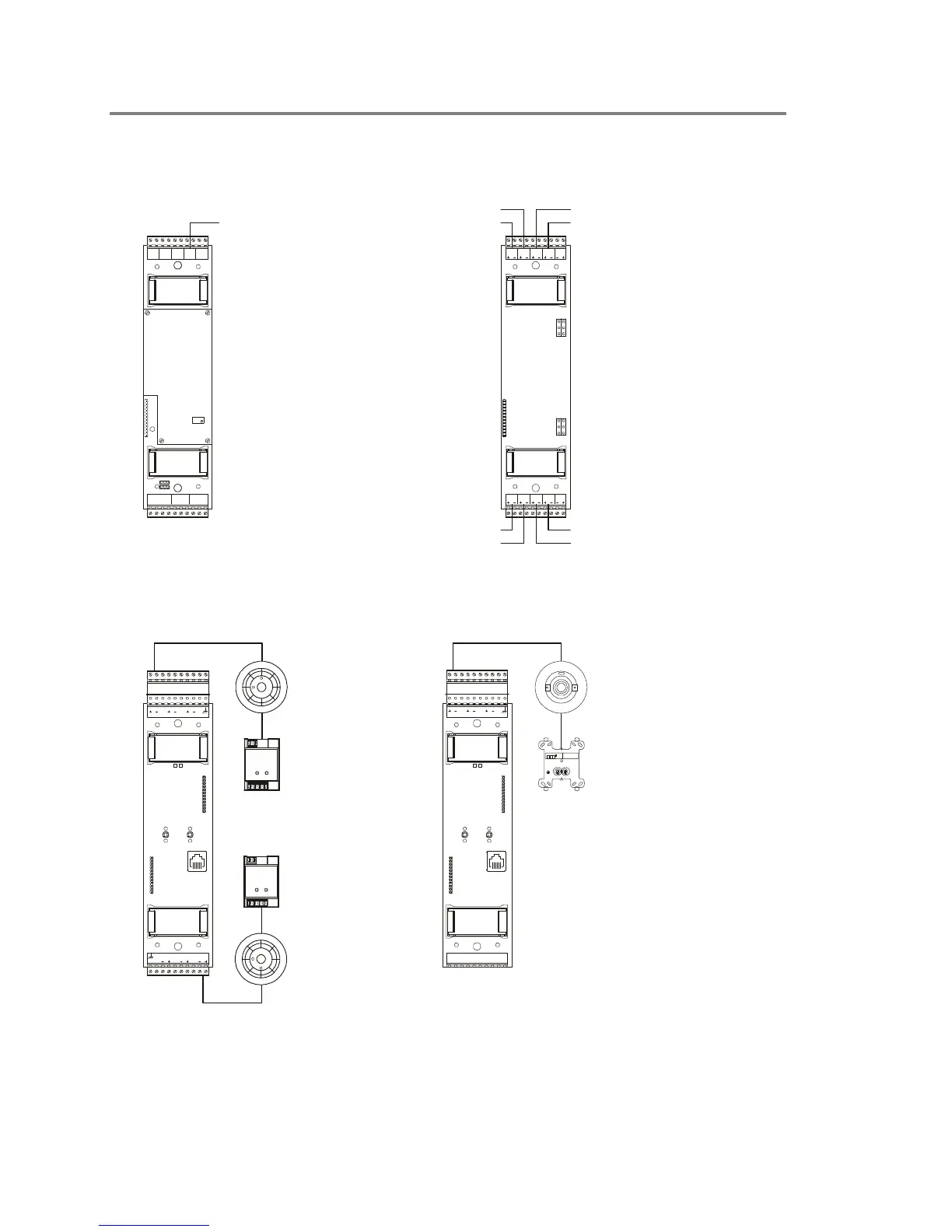
Figure A-7 shows the device logical addresses that the system
assigns to various rail modules.
TB2
TB1
J1
IDC/NAC
1
IDC/ NAC
2
IDC
3
IDC
4
NAC IN
1/2
JP1
JP3
JP2
JP4
IDC/NAC
5
IDC/ NAC
6
IDC
7
IDC
8
NAC IN
5/6
PPCC0001
PPCC0006
PPCC0004
PPCC0007
PPCC0002
PPCC0005
PPCC0003
PPCC0008
TB2
TB1
J3
J4
JP1
JP2
11
NAC /B
-+
24VDC
UNUS EDUN USEDUNUS ED U NUSE D
+--
BACK-UP
+
NAC /BNA C/A
--SS++
PPCC0001
Zoned amplifier
modules
Initiating device circuit
module
Signature controller
module
Addressable analog
controller module
OUT PUT MO DULE
SIGA2 SIGA2 SIGA2
AAS
H
BBBB
P
W
RK
M
S
2
APBB A
SIGA1
SBB
KR
WM
1
S
H
SIGA1 SIGA1
Signature detectors
PPCC0001 - PPCC0125
Sensors
PPCC0001 - PPCC0099
Signature detectors
PPCC0251 - PPCC0375
Signature modules
PPCC0126 - PPCC0250
Modules
PPCC0101 - PPCC0199
Signature modules
PPCC0376 - PPCC0500
[DEV_ADDRESS_02.CDR]
OUT PUT MO DULE
BB
LOOP1
N/C N/CBBS
H
LOOP1 LOOP1
Figure A-7: Rail module device addresses