Service and troubleshooting
EST3 Installation and Service Manual 8.7
Modules
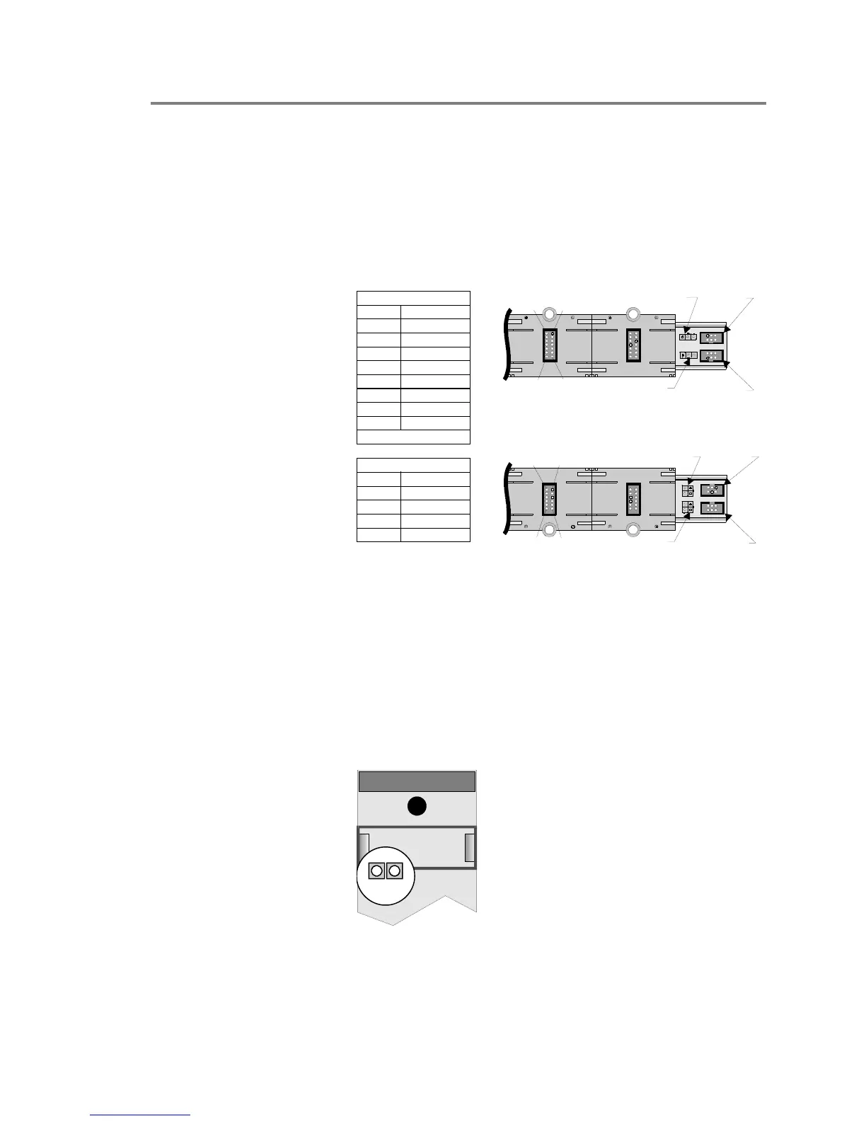
Rail signals
The figure below shows the signals normally present on a pair of
chassis rails.
Note: The panel controller and the power supply monitor module
must be installed in order to measure the voltages indicated.
J8
J9
J10
J11
To p R ai l
J9 BIN
J8 AIN
[3RAILSIG.CDR]
1
13
2
14
J10 AOUT
J11 BOUT
J8
J9
J10
J11
J8 CIN
J10 COUT
1
11
2
12
J9 DIN
J11 DOUT
Bottom Rail
Top R a i l
Pin Function
1 - 2 +6.25 VDC
3 +Sense
4 -Sense
5 -
6 +
7 -Rail Data
8 +Rail Data
9 - 10 Not Used
11 - 14 Common
Audio Data
Audio Data
Bottom Rail
Pin Function
1 - 4 +24 VDC
5 All Fail
6 - 9 Not Used
10 - 12 Ground
The DC voltages can be checked with a digital meter. Data
signals on pins 7 and 8 of the top rail can be verified by looking
at the Receive (RX) and Transmit (TX) LEDs on any module
installed on the rail.
3-PPS/M Primary Power Supply module
The transmit (TX) and receive (RX) LEDs on the Primary Power
Supply Monitor Module should flicker, indicating normal two
way communication activity with the CPU.
[PSMONLED.CDR]
TX RX
TX RX
If the 3-PPS/M Primary Power Supply is used in conjunction
with one or more 3-BPS/M Booster Power Supplies, there is