Centralized audio applications
4.14 EST3 Installation and Service Manual
ATP wiring
AMPLIFIER TERMINAL PANEL (ATP) P/N 240068
WA RN I N G
I M PRO PER C O N NEC TI O N O F TERM I N A LS
WI LL RESULT I N A FAI LURE O F PO WER SUPPLY
+
G
N
H
TB 4
120VAC
60HZ
10A MAX.
TB 5
FUSE
3AB-20A
TB2
OUT
S+
+
+++ ++SSSS
TB1
TB3
PO W ER
FA I L
PA N E L
TRBL
AC TIVITY
AMP # 1
AMP # 2
PREAM P # 2
PREAM P # 1
PWR AM P # 2
PWR AM P # 1
BATT.
OUT
BATT.
OUT
BATT. IN
24 VDC
40 AH MAX.
120 VAC OUT
WARNIN G
FO R C ON TINUED PRO TEC TIO N
AG AI NST THE RISK OF FIRE,
REPLAC E O N LY WITH SAME
TYPE 8 RATI N G FUSE.
IN
IN IN
INOUT
OUT OUT OUT
OUT
S+ +++ ++SSSS
Removable Cover
[3atpint1.cdr
Do Not Use
3-ATPINT
Do Not Use
IN
IN
P1
PREAMP 1
70V 25V
PREAMP 2
70V 25V
1
1
P2
OUT RISER
OUT RISER
OUT PRE-AMP
OUT PRE-AMP
PRE- AMP 1
PRE- AMP 2
+ - S + - S + - S
+ - S + - S + - S
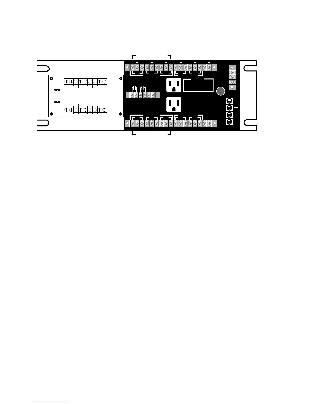
Figure 4-8: ATP with 3-ATPINT installed, rear view
ATP terminal connections
AMP POWER 1 = Type NEMA 5–15p receptacle to plug in one
amplifier. Output is rated at 120 Vac, 5 A max.
AMP POWER 2 = Type NEMA 5–15p receptacle to plug in one
amplifier. Output is rated at 120Vac 5 A max.
BATT IN - These terminals are for connection of gel cell batteries.
When the internal battery charger is enabled (J3 on the APSB
terminal board installed) a maximum of 40 Ah of gel cell batteries
can be charged.
POWER FAIL - Normally open that activates when primary
power to the amplifiers is either lost or in brownout condition.
This contact is to be supervised by Signature series input module
configured as a supervisory input.
PANEL TROUBLE - Normally open relay contacts that close
when any of the following power problems are sensed:
• Loss of 24 Vdc power
• Failure of the battery charger circuit (if enabled)
• Any blown fuse or circuit breaker
• Ground fault, if enabled
ACTIVITY = 24 Vdc should be provided to these terminals
through SIGA-CR contacts when either an alarm is present in the
system or when the system user activates the paging system.
When this input is active and the amplifier is in power fail, power
relay contacts will transfer and provide battery power to the
terminals marked BATT OUT. Each battery output terminal is
capable of providing 20 A of battery current.