Service and troubleshooting
EST3 Installation and Service Manual 8.37
Basic Signature data circuit troubleshooting
Isolating circuit and device problems
The process of isolating a problem on a Signature data circuit is
similar to that used on a conventional fire alarm Initiating Device
Circuit (IDC). An accurate and complete wiring diagram of the
data circuit installation is the best troubleshooting aid available.
When used in conjunction with the information provided by the
control panel, you should be able to easily isolate open
conditions or defective devices. The data circuit shown in Figure
8-5 will be used to illustrate basic troubleshooting techniques.
When troubleshooting Class A circuits, disconnect the circuit
from the return (SIGA/A) terminals, and temporarily jumper
both SIGA/A terminals to the respective SIGA/B terminals.
Then troubleshoot the circuit as a Class B circuit.
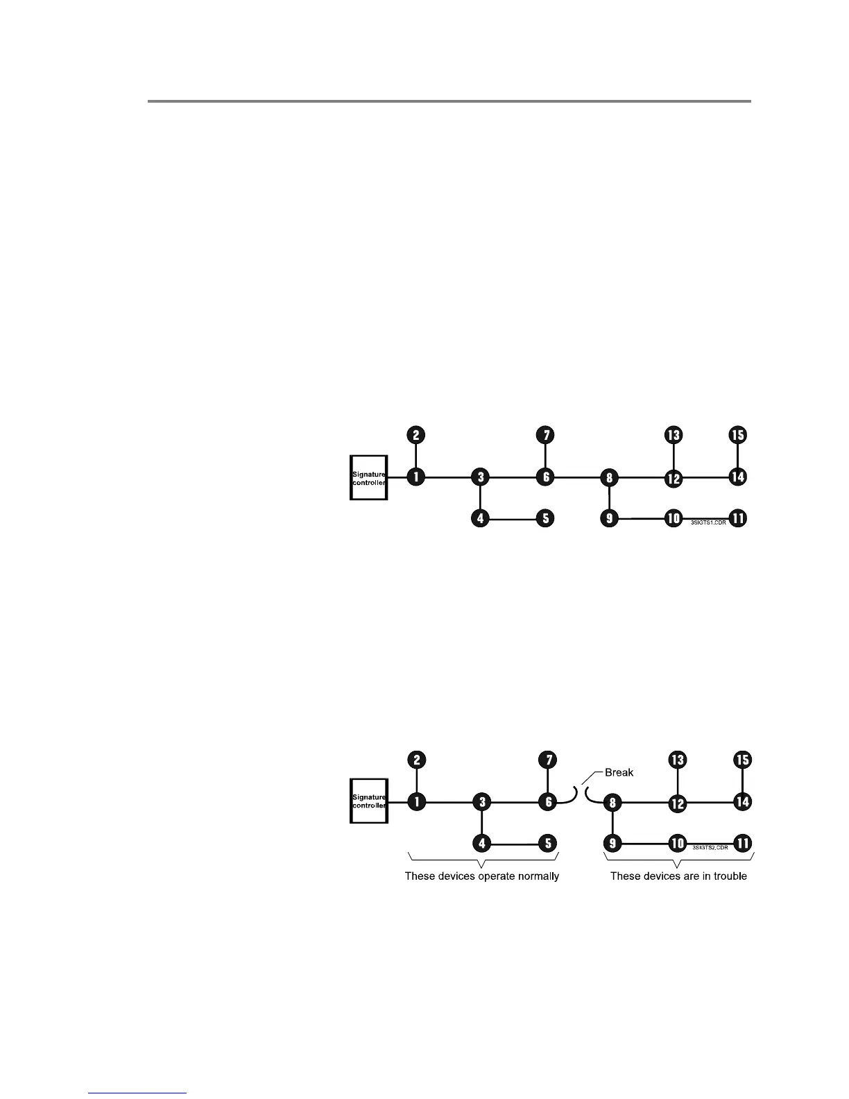
Figure 8-5: Normal circuit topology
Open circuit conditions
On a circuit with an open fault, the Signature modules will be
communicating with devices up to the break. The LCD module
will indicate a trouble condition on all devices beyond the break.
This is illustrated in Figure 8-6 where devices 1 through 7
continue to operate while devices 8 through 15 report device
troubles.
Figure 8-6: Break in circuit between devices 6 and 8
Referring again to Figure 8-6, a wire break or intermittent
connection between devices 6 and 8 is the most probable cause