Listing requirements
C.6 EST3 Installation and Service Manual
• System must be programmed for a minimum of 15 minutes
bell ring on alarm
• System must be programmed to indicate bell timeout with an
LED
• System power supply, bell power supply (24DC12), and bell
monitoring module (IDC8/4), must all be inside the ATCK
Attack Kit protected cabinet
• System must be programmed to transmit opening and
closing messages to the central monitoring station
• System must be configured using two phone lines with line-
cut detection or a single line with 24-hour test
• System must be programmed to provide closing
confirmation (ring-back) at the arming station
Central station using a 3-MODCOM
Standard: UL 1610
Minimum hardware:
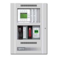
• 3-RCC7 Remote Closet Cabinet
• ATCK Attack Kit
• 3-TAMPRCC Cabinet Tamper Switch
• Central Processor Unit (CPU)
• 3-PPS/M Primary Power Supply
• Main LCD Display (LCD)
—or—
KPDISP Keypad Display
• 3-MODCOM Modem Communication Module
• 3-SAC Security Access Module
• Signature Controller Modules
• SIGA-MD Motion Detector
• SIGA-SEC2 Security Loop Module
Additional requirements:
• Standby power must provide 24 hours of standby with 15
minutes of alarm
• Maximum entry or exit delay must be 60 seconds
• System must be programmed to transmit opening and
closing messages to the central monitoring station
• System must be configured using two phone lines with line-
cut detection
—or—
3-RCC7 a single line with 24-hour test
• System must be programmed to provide closing
confirmation (ring-back) at the arming station


 To Next Page