Installation
EST3 Installation and Service Manual 5.15
78
1234
678
1234
12345678
910
IN
IN
Auxiliary/booster
supply [4]
COM
OUT
COM
OUT
Sense 2
NO
COM
NC
+
−
200 mA
AUX
47 k
EOLR
[3]
Ω
+
−
−
+
ActiveNormal
Data Out ( )
+
Data Out ( )
−
To
next
device
Data In ( )
+
Data In ( )
−
From
previous
device
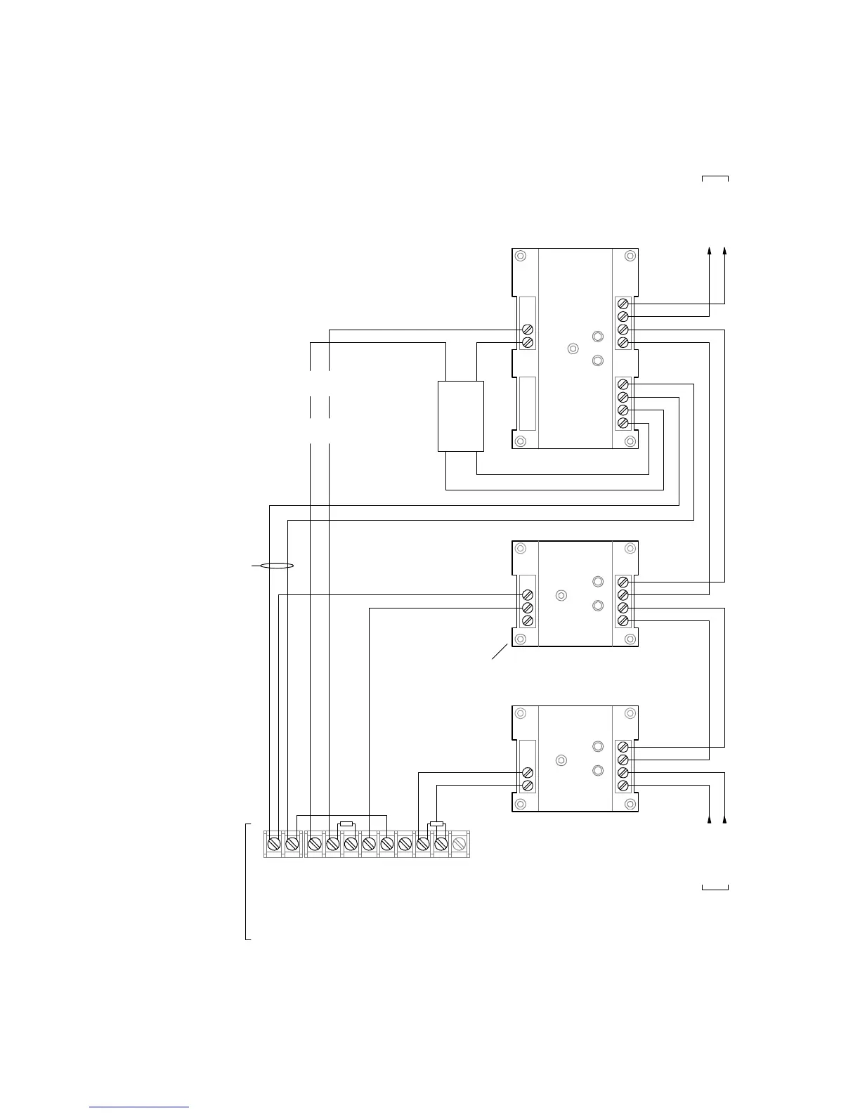
Not supervised
Model: CT1
Device type: AC Power
Personality: (3) Active B
Text 1: REMOTE_SUPPLY
Text 2: AC_FAILURE
Model: CC1 or CC1S [5]
Device type: Visible
Personality: (5) Riser Selector
Text 1: REMOTE_SUPPLY
Text 2: HRNS_&_STROBES
N.O.
C.
ORG
BLU
WHT
RED
0V
24
PAM- 1
[2]
47 k
EOLR
[3]
Ω
Model: CR
Device type:
NSCommonAlarmOutput
Personality: (8) Dry Contact
Text 1: REMOTE_SUPPLY
Text 2: HORN_SILENCE
Notes
1. All wiring is supervised and power-
limited unless otherwise noted
[2] Install a PAM-1 or equivalent listed relay
only when you are required to supervise
the 200 mA AUX circuit wiring
[3] Use part number EOL-47
[4] Configure Sense 1 and Sense 2
operation for Genesis Master mode and
NAC operation for Continuous. See the
auxiliary/booster supply documentation
for details.
[5] Use a CC1S if you want to maintain
signal synchronization across multiple
auxiliary/booster supplies on the same
Signature loop.
Sense 1
Figure 5-5: Using an auxiliary/booster supply to provide horn silence capability with two wires