System overview
EST3 Installation and Service Manual 1.7
AUDIO AUDIO AUDIO AUDIOAUDIO AUDIO AUDIO AUDIO
A IN A IN A IN A INA OUT A OUT A OUT A OUTB OUT B OUT B OUT B OUT
AUDIO AUDIO AUDIO AUDIOAUDIO AUDIO AUDIO AUDIO
B IN B IN B IN B IN
From
AUDIO DATA PRIMARY
connections on 3-ASU
CPU CPU
CPU CPU
TB2 TB2 TB2 TB2
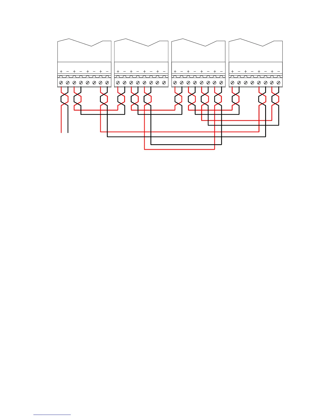
Figure 1-3: Class A network audio riser wiring
Amplifiers
Amplifiers are designed to feed a single audio zone and provide
an integral 24 Vdc visual notification appliance circuit.
Amplifier modules are available in 20-, 40-, and 95-watt
versions, with each amplifier providing a single supervised Class
B or A audio output circuit. The amplifier is configurable for
either 25 Vrms or 70 Vrms output. An independent supervised
Class B or Class A, 24 Vdc, 3.5 Amp notification appliance
circuit (NAC) is also provided on the 20- and 40-watt amplifiers
to drive notification appliances. In addition, automatic backup
amplifiers can be added on a switched common backup
configuration.
Each audio power amplifier has an integral demultiplexer,
making the 8 audio channels available to the amplifier’s input, as
directed by the system programming. Each amplifier also
contains circuitry that handles routine signal processing
functions such as channel priority.
The amplifier’s output is a dedicated, supervised, 25-, 70-Vrms
speaker circuit, which covers one audio zone in the protected
facility. Figure 1-4 is an example of an enclosure with four zone
amplifiers and a backup amplifier. In response to an alarm,
selected audio amplifiers have been connected to the required
audio channels. Note that three different audio signals are being
broadcast simultaneously.