Service and troubleshooting
8.44 EST3 Installation and Service Manual
[3MAP4.CDR]
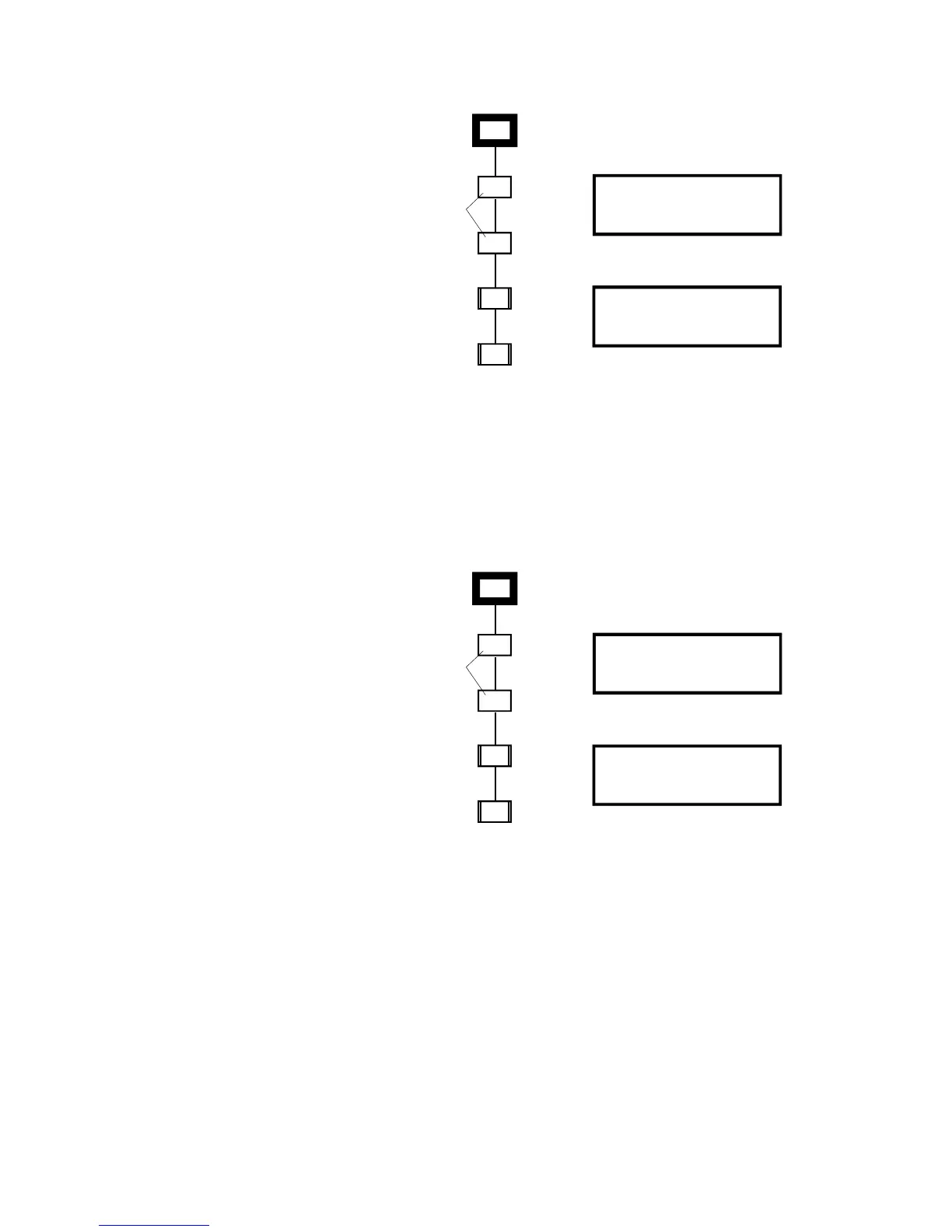
001
102
IPHS
S/N 33-1
PHS
S/N 34-1
Control Panel Display
DSDC Status Screen
The same detectors
returned to service in
new locations before
re-mapping.
CT2
S/N 49-1
P-codes 01/01
CT1
S/N 48-1
P-code 02
101
203
204
APPING
mpg0
Figure 8-14: Detectors returned to new locations during
re-mapping
Figure 8-15 shows the resultant map after re-mapping. Note that
the new S/N to panel address correlations have been made, the
IPHS is now correlated with address 102 and the PHS is
correlated with address 101. The relocated devices will now
respond as programmed for the original address location.
[3MAP5.CDR]
001
101
IPHS
S/N 33-1
PHS
S/N 34-1
Control Panel Display
DSDC Status Screen
The same detectors
returned to service in
new locations after
re-mapping.
CT2
S/N 49-1
P-codes 01/01
CT1
S/N 48-1
P-code 02
102
203
204
Figure 8-15: Final map
When a factory-new detector replaces an in-service detector,
until mapped, the new detector is operational with a default
address of 00. When the circuit is re-mapped, the new detector
will be given the address assigned to its map location. If a
factory-new detector is added over and above the expected
number of devices on the circuit, it will be operational with a
default address of 00, however the panel will be in trouble as the
“actual map” contains one more device than the “expected map.”