System overview
EST3 Installation and Service Manual 1.19
J8
J9
J10
J11
TB1
SUP
C
ALARMTROU BLE
C
N
O
NC
O
NC
-
A
C
NN
O
N
C
N
NETWO RK
+
B
+
AA
-
AUDIOAUDIO
B
-+
A IN A OU T
+--
R
X
111
T
X
R
T
S
2122
C
X
O
M
R
R
T
X
T
S
2
C
O
M
INOUT B OUT
AUDIO
++
AUDIO
B IN
--
J1
OUT PUT MODULE
SIG A 2 SI GA 2 SIG A 2
B
-
B
+
A
-
A
+
S
H
B
-
B
+
P
W
RK
M
S
2
A
-
PB
+
B
-
A
+
SIG A 1
SB
+
B
-
KR
WM
1
S
H
SIG A 1 SIG A 1
OUT PUT MODULE
SIG A 2 SI GA 2 SIG A 2
B
-
B
+
A
-
A
+
S
H
B
-
B
+
P
W
RK
M
S
2
-
PB
+
B
-
+
SIG A 1
SB
+
B
-
KR
WM
1
S
H
SIG A 1 SIG A 1
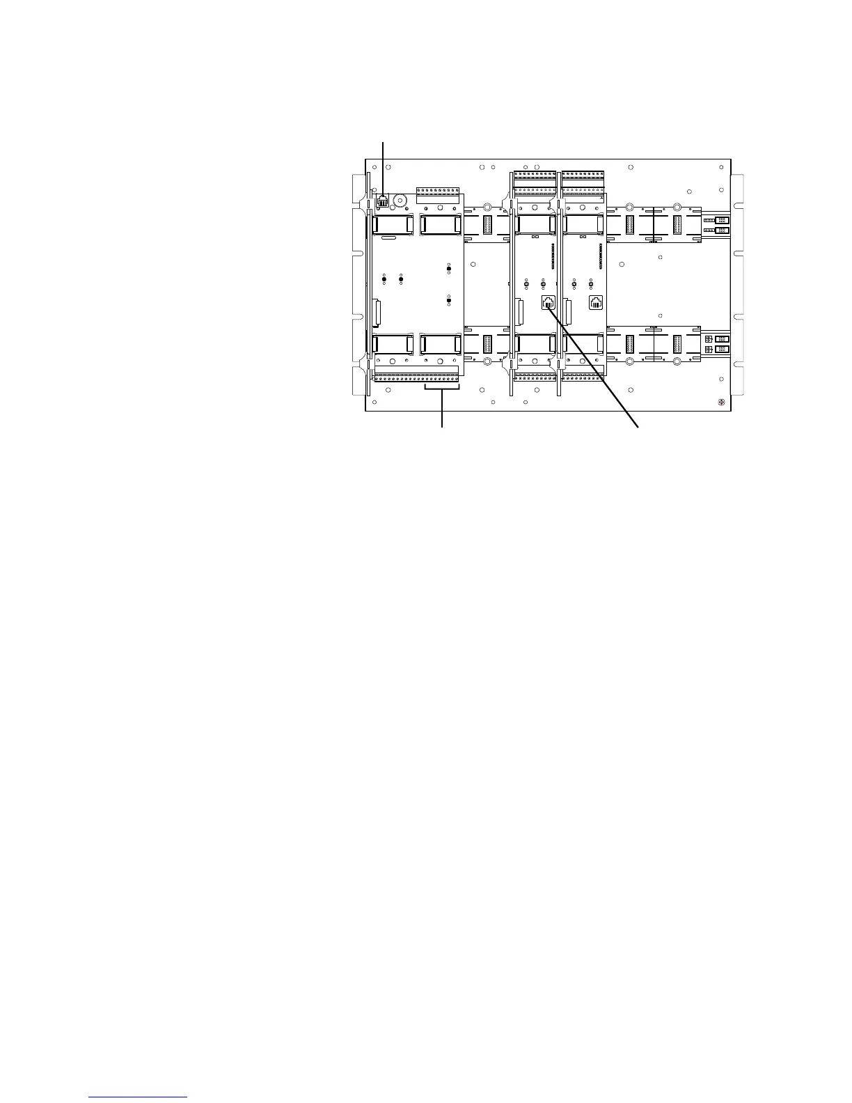
Connect here to download data to
this programmable rail module only
(single-step mode)
Connect here to download data to all three programmable
rail modules over the rail bus (network mode) or to this
programmable rail module only (single-step mode)
Optional serial ports may be used to
download over the network (3-
RS232 required)
Figure 1-12: Potential connection points for downloading data
Downloading database files over the network
A CPU module’s Network A port and its modular phone jack
share an interrupt with the module’s microprocessor. As such,
the microprocessor disables the Network A port whenever you
connect the SDU computer to the modular phone jack.
Consequently, download options differ for Class A and Class B
networks.