Applications Zoom20/30/35 Pro | 69
Station and method Enter the station values and press:
• SET OUT: to select the point and offset (center, left or right), to set out and start the measurement.
The correction from actual point to set out point is shown on the display.
• MEASURE: to measure, or select points from memory, to calculate the chainage, line and offset from
the defined element.
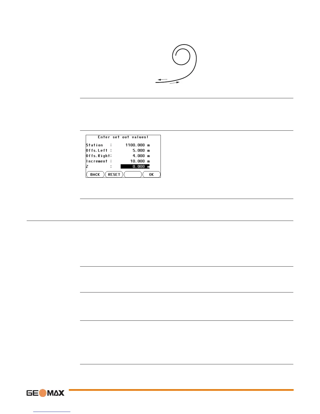
Enter set out values
Next step
• If in set out mode, press OK to begin setting out.
• Or, if in measurement mode, press ALL to measure and record.
11.13 Road 3D
11.13.1 Starting
Description Road 3D is an application used to stake out points or for as-built checks relative to a road alignment,
including slopes. It supports the following features:
• Horizontal alignments with the elements straight, curve, and spiral (entry and exit as well as partial).
• Vertical alignments with the elements straight, curve and quadratic parabola.
• Creation, view and deletion of alignments onboard.
• Use of design height of vertical alignments or manually entered heights.
• Log file via Format manager of GGO.
Road 3D methods Road 3D has the following applications:
Road 3D step-by-step
• The alignments must be continuous because geometrical gaps and chainage equations are not
supported.
• The file name for the horizontal alignment file must have the prefix ALN, for example,
ALN_HZ_Axis_01.gsi. The file name for the vertical alignment files must have the prefix PRF, for
example PRF_VT_Axis_01.gsi. File names can be 16 characters long.
• The uploaded or created road alignments are permanent and stored even if the program is closed.
• Road alignments can be deleted onboard or via GGO Data Exchange Manager.
For a spiral element: • Select the method to be used, Rad/Par or Rad/Len.
• Enter the radius and parameter, or radius and length, depending
on the method chosen.
• Select the type and direction of the spiral.
• Press OK.
Spiral type
A Spiral in
B Sprial out
4. When the element has been defined the ROAD-MAIN appears.
• Subprogram Check • Subprogram Check Slope
• Subprogram Setout • Subprogram Slope Setout
1. Create or upload road alignments.
2. Select horizontal and/or vertical alignment files.
3. Define setout/check/slope parameter.
4. Select one of the Road 3D applications.
 Loading...