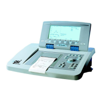
Introduction This chapter provides a brief description of the TympStar instrument hardware
assemblies, describes component and assembly removal and provides a list of
spare parts.
NOTE
Complete procedures are included for disassembly and component re-
moval
. Component replacement can be accomplished by reversing the
procedures for removal.
NOTE
The TympStar Version 1 hardware is identical to the TympStar Version 2
hardware.
WARNING
Never attempt to remove or install components while power is applied to
the TympStar instrument. When power is applied, voltages are present
within the enclosure that can cause serious personal injury or death!
WARNING
High voltage might be present in the LCD display enclosure. Never open
the LCD enclosure while power is applied to the TympStar instrument.
CAUTION
Repair or bench-testing of the TympStar instrument should be performed
only by trained personnel. The following instructions are provided for
persons who are skilled in the repair of electronic equipment.
CAUTION
The TympStar instrument is a UL-approved Middle-Ear Analyzer. Con-
sequently, only exact parts replacements should be made during repair.
Any alterations of the factory-supplied electrical or mechanical construc-
tion or components will void the UL approval.
GSI TympStar Version 1 and Version 2 Service Manual 5 - 1

 Loading...