Troubleshooting
This chapter provides descriptions of the following:
System power supply measurements
Error codes displayed on the LCD
Error messages displayed on the LCD
LCD problem symptoms and probable causes
Probe problem symptoms and probable causes
Pump problems symptoms and probable causes
Printer problems symptoms and probable causes
The hardware Diagnostic Mode
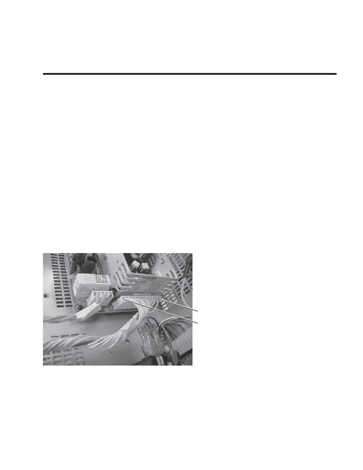
System power supply measurements
Power Supply (J2)
Pins 1,2,3 =+5.00 Volts DC
Pins 4,5,6,7 ground reference
Pins 8, 9 =+24 VDC
Pins 10,12= 0VDC
Pin 11= -12VDC
Pin 13= +12VDC
Pin 1 (Red wire)
Pin 13
Reference J2 - Set to +5.00 (+or-10mVDC)
GSI TympStar Version 1 and Version 2 Service Manual 8 - 1
 Loading...