Chapter 5
The Tympstar pump is unique to this product. The GSI33 pump assembly
should not be used as a replacement.
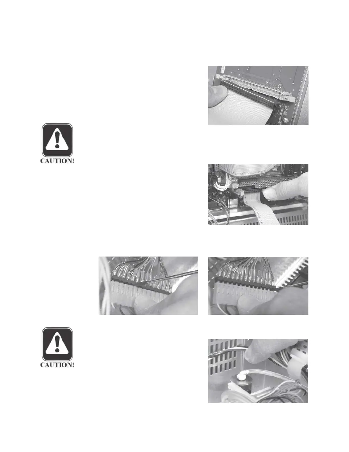
Step 1
Remove the 60-pin digital signal
cable from the digital board mounted
under the cover by disengaging the
two cable connector retainer tabs and
pulling the cable straight out of the
connector housing.
CAUTION
During reassembly, the flat 60-pin digital signal cable must be folded to
the rear out over the pump, not to the front over the analog board.
Step 2
Remove the 20-pin digital signal
cable from the rear of the digital board
mounted under the cover by disengag-
ing the two cable connector retainer
tabs and pulling the cable straight out
of the connector housing.
Step 3
Disconnect the pump from the digital board by carefully separating the pump
cable connector. Use a flat-edge screwdriver to gradually pry the connector
apart.
CAUTION
Do not rush this process, or apply
excessive force.
The cable connec-
tor is fragile and will break if bent
or stressed.
Step 4
Remove the probe pneumatic tube
from the holding valve by pulling the
tube straight off the valve connection.
Grason-Stadler
 Loading...