Home
GSi
Measuring Instruments
TYMPSTAR Series
GSi TYMPSTAR Series User Manual
5
of 1
of 1 rating
224 pages
Give review
Manual
Specs
To Next Page
To Next Page
To Previous Page
To Previous Page
Loading...
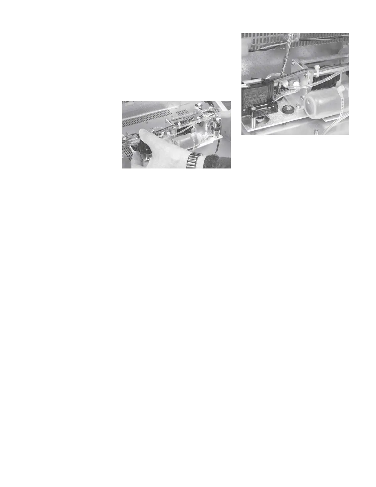
Di
sassembly
S
te
p 5
Usin
g
a
shor
t
Philip
s
screwdrive
r,
fully
loosen
the
four
retaining
screws
around
the
bellows
on
the
bottom
of
the
pump
assembly
.
The
pump
assem
-
bly
can
now
be
lifted
out
of
the
chas
-
sis.
GSI
T
ym
p
St
ar
V
ersion
1
and
V
ersion
2
Service
Manu
a
l
5 - 7
144
146
Table of Contents
Default Chapter
6
Table of Contents
6
Version 2 Specifications
21
Standards
21
Sensitivity Ranges
22
Probe Signal (Sinusoidal)
22
Pneumatic System
23
Acoustic Reflex Activating (Stimulus) Signal
23
Stimulus
25
Presentation Control
25
Environmental
26
Warm-Uptime
26
Calibration Stability
27
Connectors
27
Electrical
28
Suppliedaccessories
29
Mechanical
29
Materials of Manufacture
29
Calibration Requirements
40
Operation Summary
41
Front Panel Controls
41
Hardkeys
42
Tymp
42
Reflex
42
Etf
42
Special
42
Print
42
Remote
42
Data Transfer
42
Pressure Control
42
Manual
42
Start
43
Stimulus
43
Intensity
43
Present
43
LCD Hardkeys
43
Clear
43
Erase
43
Return
43
Softkeys
43
Menus and LCD Screens
44
Menus
44
Program Modes
45
Version 1 Probe Tone Frequencies
45
Version 2 Probe Tone Frequencies
45
Version 1 LCD Graphic Traces
45
Version 2 LCD Graphic Traces
45
Probe Lights
46
LCD Screen
46
Erasing and Clearing Test Data
47
Version 2 External Reflex Test Stimuli
47
Paging Test Data
47
Version 2 Cursor
48
Printing Tests
48
Preparing an External Printer
48
Setting the Printer Parameters
49
Left Column Printout Data
50
Color or Black and White
50
Changing Instrument Versions
51
Changing from a Version 2 to a Version 1
51
Switching to V1 Temporarily
52
Switching Back to V2
52
Switching to V1 Permanently
52
Changing from a Version 1 to a Version 2
53
Obtaining a License Code
54
Replacing the V1 Probe with a V2 Probe
55
Switching to Version 2 Software
56
Version 1 Test Procedures
57
Tymp Diagnostic
57
Manual Tymp
57
Tymp Screening
58
Reflex Threshold
58
Automatic Auto Zero
58
Mark Threshold
59
Reflex Threshold Seeking
59
Reflex Decay
60
Eustachian Tube Function
60
Pressure Swallow Test (Intact TM)
60
Perforated Ear Test (Perforated TM)
60
Auto Sequence Testing
61
Programming Auto Sequence Tests
61
Version 2 Test Procedures
62
Tymp Diagnostic
62
Manual Tymp
63
Tymp Screening
63
Reflex Threshold
64
Automatic Auto Zero
65
Mark Threshold
65
Reflex Threshold Seeking
65
Reflex Decay
66
Acoustic Reflex Latency Test (ARLT)
66
Acoustic Reflex Sensitization (A.R. SENSI)
67
Eustachian Tube Function
68
Pressure Swallow Test (Intact TM)
68
Perforated Ear Test (Perforated TM)
68
Multiple Frequency Tympanometry (MULTIPLE Hz)
69
Auto Sequence Testing
70
Programming Auto Sequence Tests
71
Calibration
73
Introduction
73
When to Calibrate the Tympstar
74
Calibration Requirements
74
Complete Calibration Sequence
74
Routine Calibration Sequence
75
Preparing for Calibration
76
Tools and Equipment Required
76
Cleaning the Probe and contra Phone
76
Probe
76
Contra Phone
77
Cal/Normal Switch
78
Cal Option DIP Switch
78
Switch 1: Factory Use Only
79
Switch 2: Gsi/Custom RTL Transducer Calibration
79
Switch 3: Unused
79
Switch 4: Unused
79
Switch 5: Unused
79
Switch 6: Diagnostic Mode
79
Hardware Diagnostics
80
Dac Levels
81
Ipsi Source
83
Ipsi On/Off
83
Contra Source
83
Contra On/Off
84
Mux Inputs
84
Probe/Filer
85
Routing
86
Probe On/Off
87
Ports Diag
87
Rs-232 Int. On/Off
87
Parallel On/Off
88
Misc. Diag
89
Calendar Clock
90
Display & Leds
92
Keys
93
Dip Switches
94
Eeprom
94
Software Timer
95
Watchdog Timer
96
Error Log
97
Switch 7: Self-Cal
98
Switch 8: Load Default Calibration Data
98
Probe Serial Number
98
Resolving Problems
99
Calibration Procedures
100
Hardkeys
100
Softkeys
101
Printing Calibration Sheets
102
Adjusting Cal HL and Target SPL Levels
103
Custom Transducers
104
Transducer Connections
104
Calibration Requirements
105
Complete Calibration Sequence
105
Routine Calibration Sequence
105
Tympstar Version 1 Calibration
105
Version 1 Calibration Procedures
106
Self-Cal
106
Loading Default Data
107
Contra, Ipsi and Probe Tone Calibration
108
Contra SPL Cal
108
Ipsi SPL Cal
109
Y Cal
111
Altitude Cal
111
Pressure Cal
114
Set Ambient
114
Set -600/400
116
Leak Rate
117
Verify Cal
119
Diagnostic
121
Returning to the Normal Test Mode
122
Tympstar Version 2 Calibration
123
Calibration Requirements
123
Complete Calibration Sequence
123
Routine Calibration Sequence
123
Version 2 Calibration Procedures
124
Self-Cal
124
Loading Default Data
125
Contra, Ipsi and Probe Tone Calibration
126
Contra and Ipsi Cal
126
External Input Calibration
127
Click Calibration
127
Contra SPL Cal
128
Ipsi Channel
128
Contra Channel
129
Ipsi SPL Cal
131
Ipsi Channel
131
Contra Channel
132
Probe Tone SPL Cal
134
Y/B/G Cal
136
Altitude Cal
136
Pressure Cal and Diagnostics
138
Returning to Normal Test Mode
138
Disassembly
139
Introduction
139
Disassembly Procedure
141
Tools Required
141
Opening the Cover
141
Removing the Analog Board
142
Removing the Pump
144
Removing the Power Supply
146
Removing the Power Module
147
Fuse Holder
147
Removing the Printer Board
149
Removing the Digital Board
155
Removing the LCD
158
Removing the LCD Front Panel Label (Softkey Panel)
165
Removing the Instrument Front Panel Label
167
Removing Panel Keypads
167
System Level Parts
169
General
169
Assembly Drawings
169
Case/Chassis
170
Overall Assembly
172
LCD Assembly
173
Instrument Assembly
176
Labels
177
Printer Assembly
179
Hardware Description
181
General
181
System Boot Sequence
181
Pre-CP Control
181
Main()
181
Set_Op_Mode()
183
Tymp_Sk()
184
Interconnection Diagram
185
Block Diagram Description of Assemblies
186
LCD Assembly
186
Printer
186
Probe
186
Pump
186
Digital Board
187
PC104 Board
187
Analog Board
187
Power Supply Board
188
Printer Board
188
System Assembly Diagram
189
Troubleshooting
191
System Power Supply Measurements
191
Power Supply (J2)
191
Power Supply (Set +5VDC)
192
Analog Board (J7)
192
Analog Board (J6)
192
Analog Board (J10)
193
Digital Board (J28)
193
Digital Board (J34)
193
Printer Board (Full View)
194
Printer Board (J6)
194
Printer Board (J4)
194
Printer Board (J8)
195
Pressure Potentiometer (Digital Board)
195
Error Codes
196
CP Error Codes
196
SP Error Codes
206
Error Messages
209
LCD Problem Symptoms and Probable Causes
212
Probe Problem Symptoms and Probable Causes
212
Pump Problem Symptoms and Probable Causes
213
Printer Problem Symptoms and Probable Causes
213
Hardware Diagnostic Mode
214
Functional Description
214
Pressure A/D MUX
214
MIC. MUX
215
DAC Levels
215
Routing
215
IPSI/CONTRA and OSC L/Osc 2
216
5
Based on 1 rating
Ask a question
Give review
Questions and Answers:
Need help?
Do you have a question about the GSi TYMPSTAR Series and is the answer not in the manual?
Ask a question
GSi TYMPSTAR Series Specifications
General
Brand
GSi
Model
TYMPSTAR Series
Category
Measuring Instruments
Language
English
Related product manuals
GSi TYMPSTAR 2
224 pages
GSi TYMPSTAR PRO
164 pages
GSi JK300HP
186 pages
 Loading...