Disassembly
Removing the
Step 1
printer board
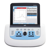
Disconnect the printer power cable
from the printer board by pulling the
cable connector straight off the hous-
ing.
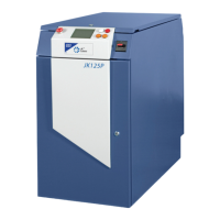
Step 2
Disconnect the two printer signal cables by pulling the cable connectors straight
off the housings.
Printer data
Printer photo-eye
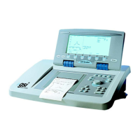
Step 3
Disconnect the 20-pin digital signal
cable by pulling the cable connector
straight out of the housing.
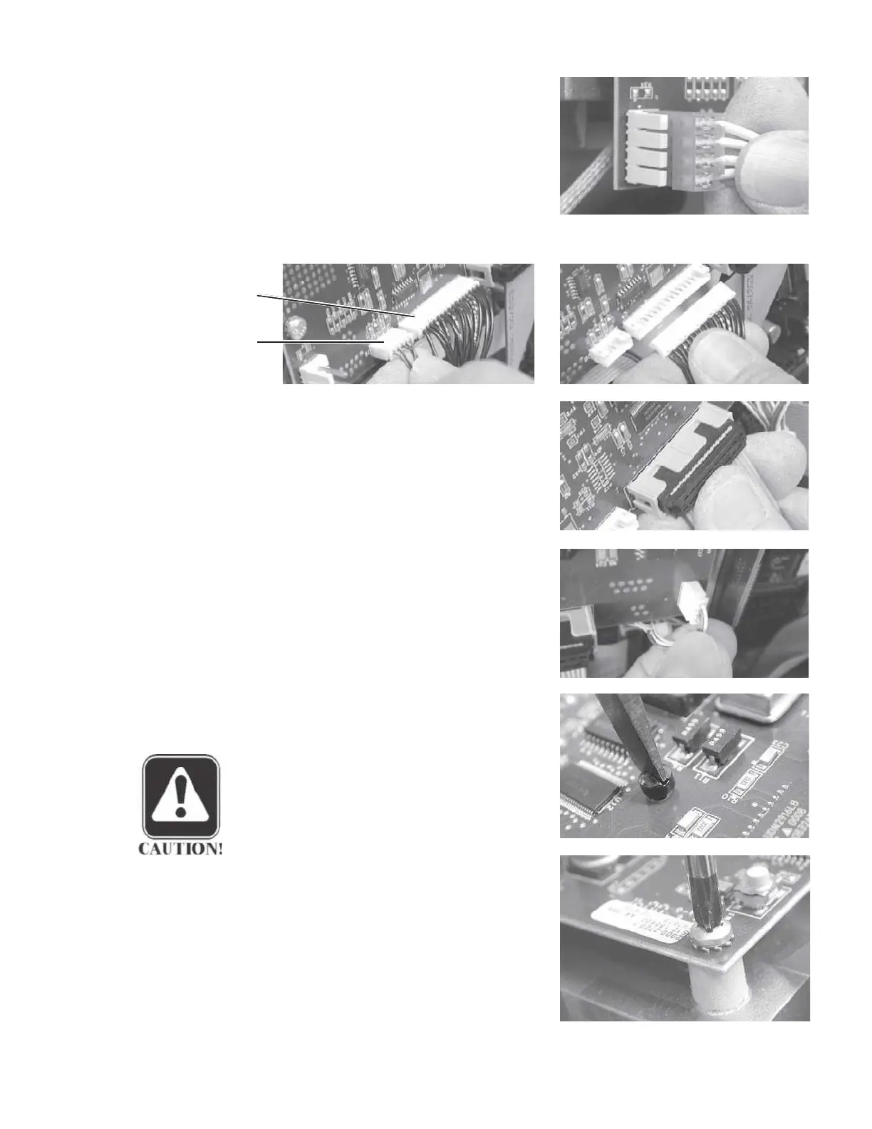
Step 4
Disconnect the printer motor connec-
tor by pulling it straight away from
the board.
Step 5
Remove the plastic screw from the
printer board.
CAUTION
The plastic screw must be replaced
in this position during reassembly.
Step 6
Remove the three metal screws from
two upper and lower left corner of the
board.
Step 7
Remove the printer board from the
chassis.
GSI TympStar Version 1 and Version 2 Service Manual
5 - 11
 Loading...