setting the various circuits to desired
known states to facilitate troubleshooting. During normal operation, the control pro-
cess and signal processor control the circuitry, and in most cases they are not set in
steady state conditions; therefore troubleshooting is difficult.
All the blocks of circuitry that can be selected and set will be described in the
following paragraphs. Also, states and conditions that exist when default data is
loaded into memory and operating parameters are chosen (i.e., 1 kHz into a 2 cc
cavity, etc.) will be indicated.
The following text describes the circuit functions that can be controlled by the Diag-
nostic Mode.
NOTE:
GSI will make available instructions, schematic diagrams and other system
drawings as it deems appropriate to be repaired in the field.
The Pressure Multiplexer is a CMOS analog switch located on Analog Schematic.
This multiplexer circuit’s main function during normal mode operations, is to route
the probe pressure transducer signal or manual pressure pot signal to the control
processor A/D converter (digital board schematic). There are six additional signals
connected to it, which during initialization are monitored as integrity checks to pro-
vide diagnostic information. These additional signals are as follows:
1) Ipsi power amplifier output (Analog Schematic)
2) Contra power amplifier output (Analog Schematic)
3) Mic. level control DAC (Level Control Schematic)
4) Probe tone level control DAC (Level Control Schematic)
5) Ipsi level control DAC (Level Control Schematic)
6) Contra level control DAC (Level Control Schematic)
The various signals can be routed to the Control Processor A/D by selecting the
MUX INPUTS softkey, then the PRESSURE MUX softkey.
Grason-Stadler
Chapter 8
Hardware Diagnostic mode
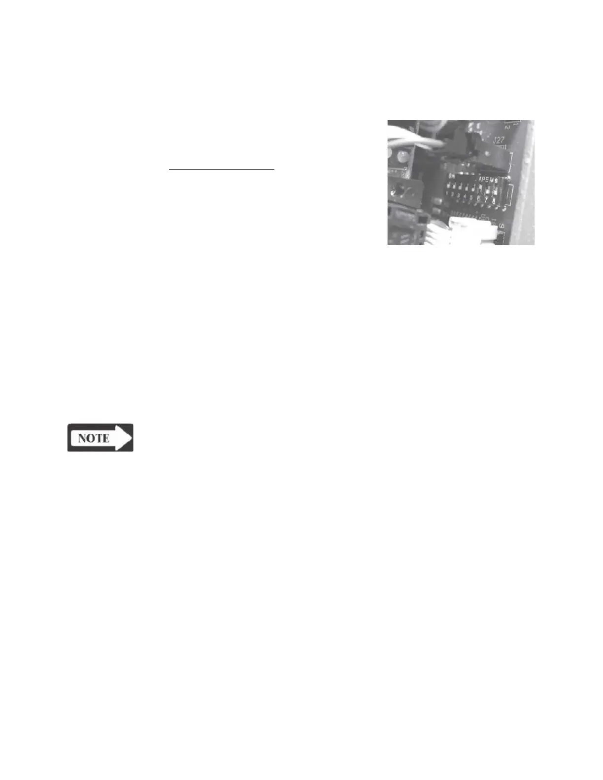
The Hardware Diagnostic Mode is entered by
setting the Calibraion Options DIP switch 6 to
ON and entering the Cal
Mode
. Refer to
Chapter 4: Calibration for detailed instructions
regarding the Cal Mode and Diagnostic Mode.
The Hard-ware Diagnostic Mode gives you
complete control of the hardware circuitry in
the GSI TympStar. The LCD will display
selection possibilities that are available for
 Loading...