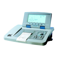
General
This chapter provides system-level descriptions of the TympStar hardware and hard-
ware interconnections. Hardware is shown as assembly diagrams, block diagrams
and interconection diagrams and include typical signal levels at the input/output inter-
faces of factory-calibrated hardware assemblies. The chapter begins with a de-
scription of the system boot sequence.
NOTE:
GSI will make available instructions, schematic diagrams and other system
drawings as it deems appropriate to be repaired in the field.
System boot sequence
Pre-CP Control
1
. TympStar is turned ON - PC104 is powered and FLASH BIOS does minimal
system check (RAM check, DOC present check, etc) and loads boot sector(s)
of the DOC (which launches the PharLap OS).
2. At this time, the PharLap OS is not loaded, the CP.EXE program is not loaded
and the SP should be held in reset. The printer board should be powered and
the printer firmware should be running and idle.
3. PharLap OS boots on DOC – after OS is booted the CP.EXE program is
loaded and run under the PharLap OS.
4. Once the CP.EXE program is completely loaded in memory, it begins running –
after a small amount of compiler generated startup code (to initialize globals, set
up stacks, etc) control is transferred to the main() routine which is the start of the
CP software world.
Main() 5. The GFX (Graphics) subsystem is initialized (PharLap uses an package called
PEG which is integrated into the OS). Both the LCD and CRT are driven in the
proper resolution. Current FLASH BIOS has the LCD enabled (i.e. we don’t
have to specifically turn it on in software) so at this point, a complete reverse
video screen (white on the CRT) should be shown. The graphics driver thread
is started in software to handle all LCD/CRT output.
6. The TST subsystem is initialized by starting the Test thread. This is responsible
for handling virtually all of the different TympStar tests (Tymp, Reflex,ARLT,
etc). This thread always runs and sits idle waiting for requests to run a test.
7. The ERR subsystem is initialized – the ability to generate and log failsafe codes
can be done from this point forward.
GSI TympStar Version 1 and Version 2 Service Manual 7 - 1

 Loading...