Issue 08/2013 Page 90
MAPLA- Modular energy supply system for load lifting magnets
Installation and commissioning
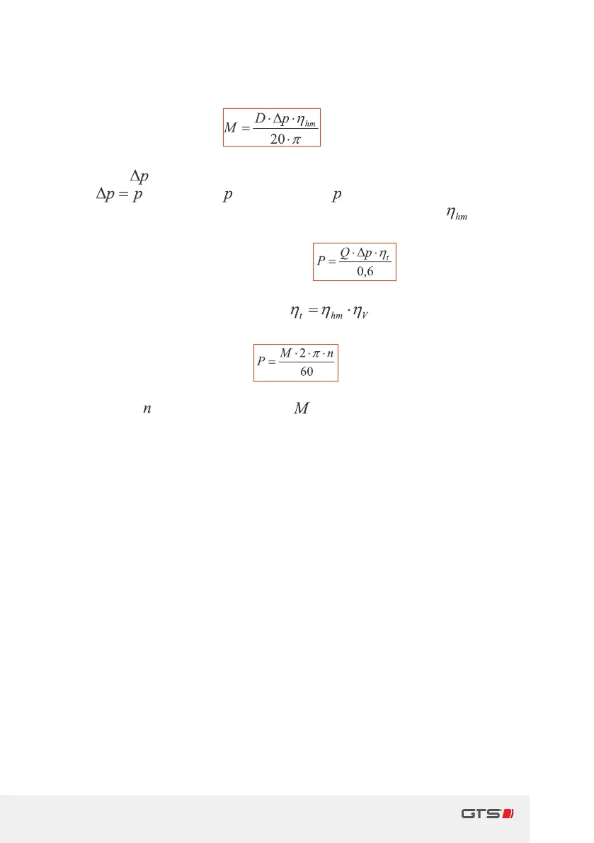
Arrangement of the hydraulic drive
applied torque of the motor: in[Nm]
with the pressure dierence between the input and output of the
hydro-motor
calculated in[bar]
e.g.via
Pump in total
-
backing-up valve
-
counter-pressure tank
in bar
and with the hydraulic/mechanical eciency of the hydro-motor
in[
%
/
100
] caused by losses due to friction, etc.
applied output from the motor to the shaft:
in[Watt]
with the overall eciency of the engine
in[
%
/
100
]
Conversion of torque into output:
in[Watt]
with the speed
[
revs.
/
min
] and torque in[ Nm]
Operating aGTS iMAPLA at SunFab Hydro-Motors
GTS oers options in the arrangement of the hydraulic drive through the
use of special ow rate control valves. The indicated working pressures
and volume ows in the table are to be used using the SunFab axial piston
hydraulic motors (optionally also) oered by GTS. Other motor types can also
be adapted by avariable assembly of plate and avariety of couplers. Contact
GTS special adjustments and special layouts and special layouts.
Ö Overview table for the operation of aGTS iMAPLA on SunFab hydraulic
motor generator types: BG132 2-pole and BG160 4-pole., page91