APS-7000 Programming Manual
20
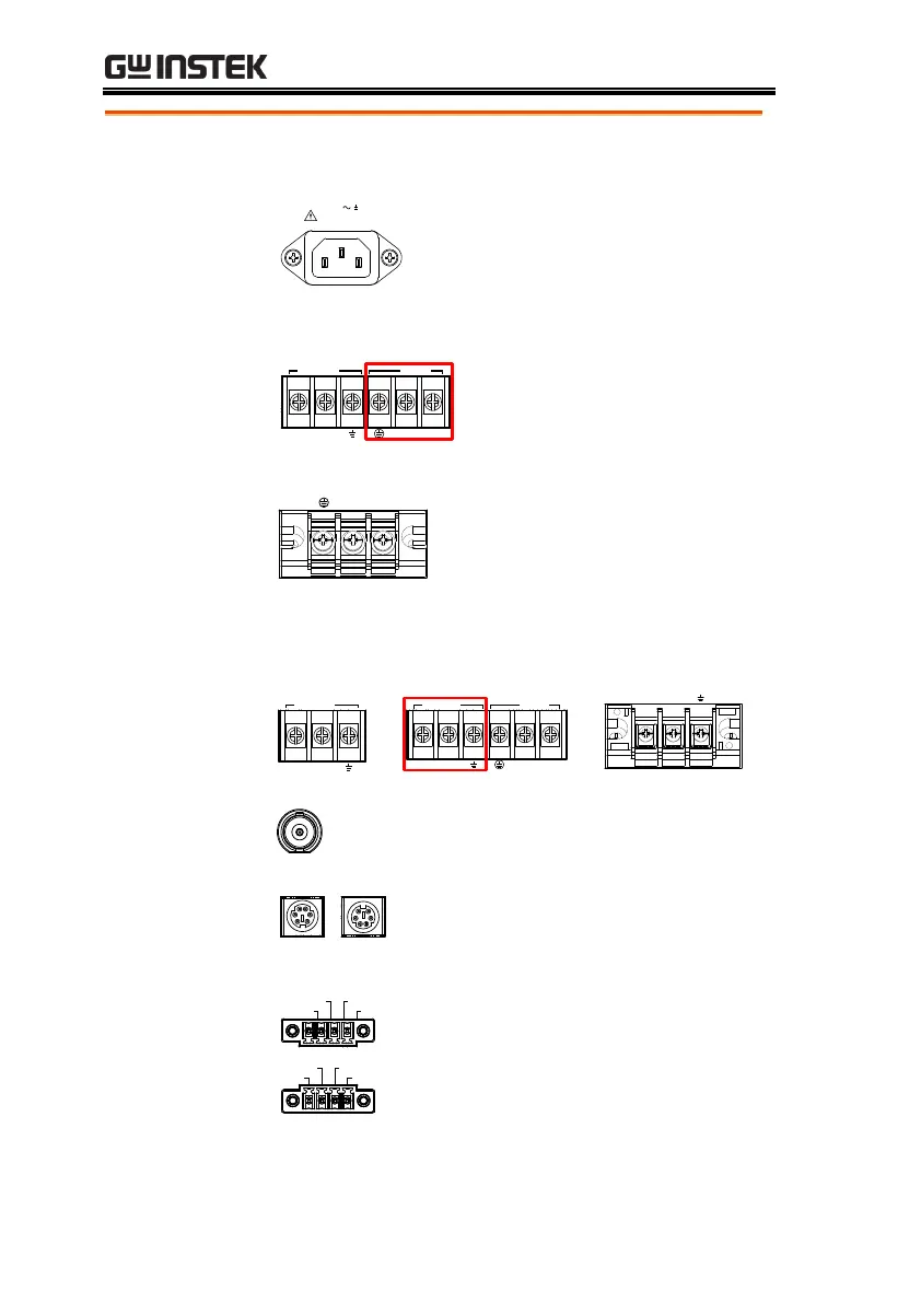
115 / 230V 15%
50 / 60Hz
1.8kVA MAX.
Voltage Input: 115/230±15% VAC;
Line frequency: 50Hz/60 Hz
(Automatically switchable)
Voltage Input: 115/230±15%
VAC ; Line frequency:
50Hz/60 Hz (Automatically
switchable)
Voltage Input: 230±15% VAC ;
Line frequency: 50Hz/60 Hz
Rear Voltage
Output Socket
BNC socket. This socket will output a
signal of approximately 10V when the
output is on.
Signal output
APS-7050
APS-7100
APS-7200
APS-7300
Connector for monitoring PASS, FAIL
and PROCESSING output signals
when using the Program mode.
Trigger Out
Trigger In
Out On / Off
COM
APS-7200 and APS-7300
Trigger Out
Trigger In Out On / Off
COM
APS-7050 and APS-7100
Connector for controlling the
TRIGGER IN, TRIGGER OUT and
OUT ON/OFF states.
 Loading...