Modules and transducers
108 A03031_24_E00_01 HBM: public QuantumX
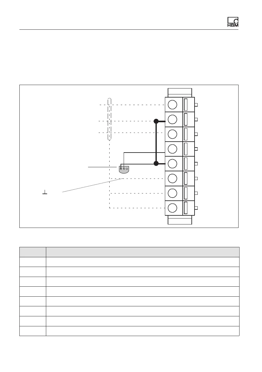
8.10.1 MX1601B pin assignment
So that insertion or removal of a transducer connection can be unmistakably
identified, Pin 2 and Pin 5 in the connector plug must be bridged! If this bridge
is missing, no measurement values will be recorded at the connection!
1
2
3
4
5
6
7
8
1
2
3
1‐wire EEPROM
(Maxim DS24B33+)
view from below
1
2 Data
3 No function
Bridge
Fig. 8.16 Pin arrangement of connection plug, view from the connection side
Pin Connector
1 Voltage output 10 V (+), 100 mV (+), IEPE (+)
2 Signal ground, TEDS (-)
3 Current input 20 mA (+)
4 TEDS (+)
5 Always connect with Pin 2! (Plug-in detection)
6 Active sensor supply (+)
7 Active sensor supply (-)
8 Housing (shield connection)