226 Programming: Programming Contours
6.4 Path Contours—Cartesian Coordinates
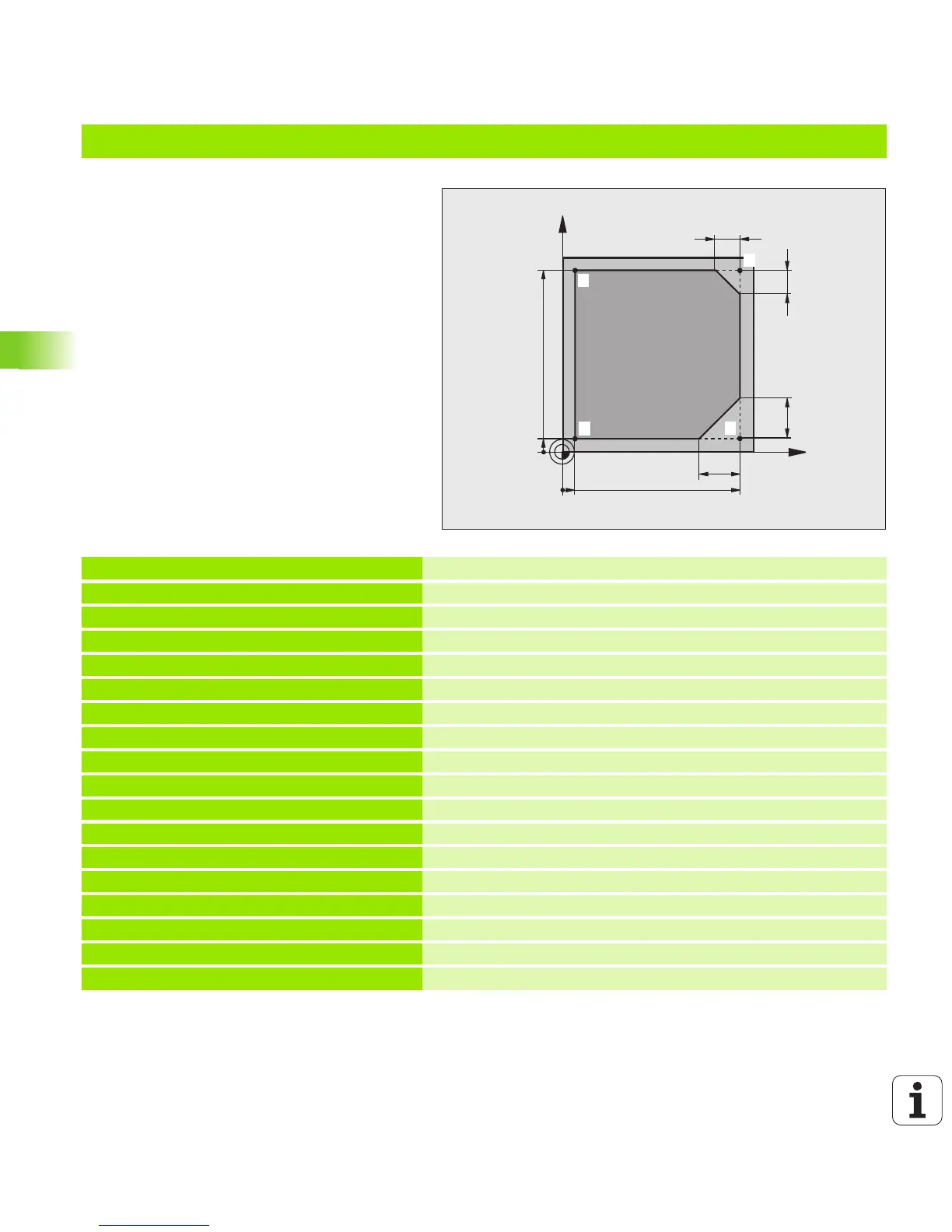
Example: Linear movements and chamfers with Cartesian coordinates
0 BEGIN PGM LINEAR MM
1 BLK FORM 0.1 Z X+0 Y+0 Z-20
Define blank form for graphic workpiece simulation
2 BLK FORM 0.2 X+100 Y+100 Z+0
3 TOOL CALL 1 Z S4000
Call tool in the spindle axis and with the spindle speed S
4 L Z+250 R0 FMAX
Retract tool in the spindle axis at rapid traverse FMAX
5 L X-10 Y-10 R0 FMAX
Pre-position the tool
6 L Z-5 R0 F1000 M3
Move to working depth at feed rate F = 1000 mm/min
7 APPR LT X+5 Y+5 LEN10 RL F300
Approach the contour at point 1 on a straight line with
tangential connection
8 L Y+95
Move to point 2
9 L X+95
Point 3: first straight line for corner 3
10 CHF 10
Program chamfer with length 10 mm
11LY+5
Point 4: 2nd straight line for corner 3, 1st straight line for corner 4
12 CHF 20
Program chamfer with length 20 mm
13LX+5
Move to last contour point 1, second straight line for corner 4
14 DEP LT LEN10 F1000
Depart the contour on a straight line with tangential connection
15 L Z+250 R0 FMAX M2
Retract in the tool axis, end program
16 END PGM LINEAR MM

 Loading...


