62 First Steps with the iTNC 530
1.3 Programming the First Part
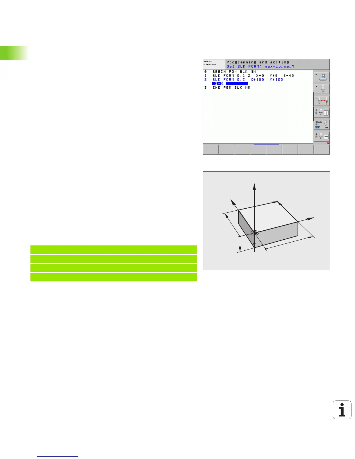
Define a workpiece blank
Immediately after you have created a new program, the TNC starts the
dialog for entering the workpiece blank definition. Always define the
workpiece blank as a cuboid by entering the MIN and MAX points,
each with reference to the selected reference point.
After you have created a new program, the TNC automatically initiates
the workpiece blank definition and asks for the required data:
U Spindle axis Z?: Enter the active spindle axis. Z is saved as default
setting. Accept with the ENT key
U Def BLK FORM: Min-corner?: Smallest X coordinate of the workpiece
blank with respect to the reference point, e.g. 0. Confirm with the
ENT key
U Def BLK FORM: Min-corner?: Smallest Y coordinate of the workpiece
blank with respect to the reference point, e.g. 0. Confirm with the
ENT key
U Def BLK FORM: Min-corner?: Smallest Z coordinate of the workpiece
blank with respect to the reference point, e.g. -40. Confirm with the
ENT key
U Def BLK FORM: Max-corner?: Largest X coordinate of the workpiece
blank with respect to the reference point, e.g. 100. Confirm with the
ENT key
U Def BLK FORM: Max-corner?: Largest Y coordinate of the workpiece
blank with respect to the reference point, e.g. 100. Confirm with the
ENT key
U Def BLK FORM: Max-corner?: Largest Z coordinate of the workpiece
blank with respect to the reference point, e.g. 0. Confirm with the
ENT key
Example NC blocks
Further information on this topic
Defining the workpiece blank: (see page 108)

 Loading...


