HEIDENHAIN iTNC 530 487
12.6 Three-Dimensional Tool Compensation (Software Option 2)
12.6 Three-Dimensional Tool
Compensation (Software
Option 2)
Introduction
The TNC can carry out a three-dimensional tool compensation (3-D
compensation) for straight-line blocks. Apart from the X, Y and Z
coordinates of the straight-line end point, these blocks must also
contain the components NX, NY and NZ of the surface-normal vector
(see “Definition of a normalized vector” on page 488).
If, in addition, you want to carry out a tool orientation or a
three-dimensional radius compensation, these blocks need also a
normalized vector with the components TX, TY and TZ, which
determines the tool orientation (see “Definition of a normalized
vector” on page 488).
The straight-line end point, the components for the surface-normal
vector as well as those for the tool orientation must be calculated by
a CAM system.
Application possibilities
Use of tools with dimensions that do not correspond with the
dimensions calculated by the CAM system (3-D compensation
without definition of the tool orientation).
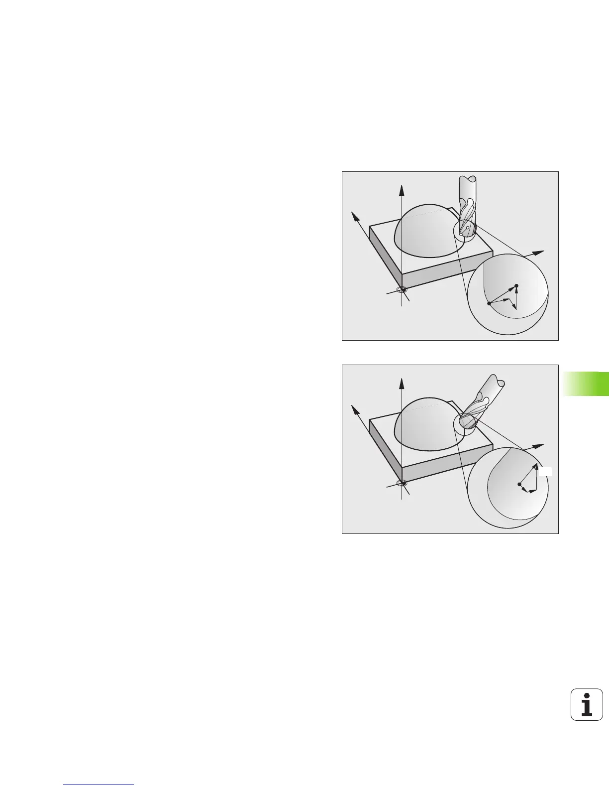
Face milling: compensation of the milling machine geometry in the
direction of the surface-normal vector (3-D compensation with and
without definition of the tool orientation). Cutting is usually with the
end face of the tool.
Peripheral milling: compensation of the mill radius perpendicular to
the direction of movement and perpendicular to the tool direction
(3-D radius compensation with definition of the tool orientation).
Cutting is usually with the lateral surface of the tool.

 Loading...


