4.26 Lockout Switch Assembly
Chapter 4: Removal, Replacement, and Adjustment Procedures
Page 4 - 66 Affinity® Three Birthing Bed and Affinity® Four Birthing Bed
Service Manual (MAN272 REV 4)
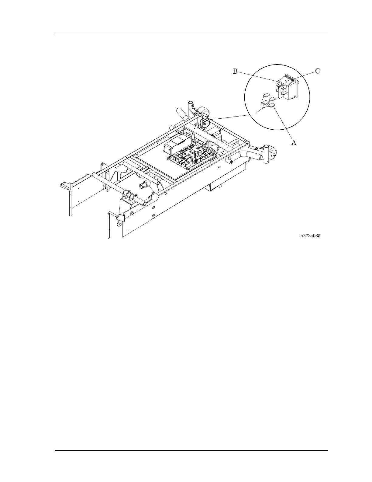
Figure 4-35. Lockout Switch Assembly
Replacement
1. To install the replacement lockout switch assembly (B), reverse the
removal procedures.
2. Ensure that the wiring connector (A) is firmly connected to the lockout
switch assembly (B).
3. Do the “Function Checks” on page 2-4.