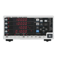
Pressing on the first row, on the second row, on the third row, or on the fourth row of the measured
value display switches the display parameter, causing the selected display parameter to light up.
V Voltage (U)
A Current (I)
W Active power (P)
VA Apparent power (S)
var Reactive power (Q)
PF Power factor ()
° Phase angle (φ)
V Hz Voltage frequency (f)
A Hz Current frequency (f)
Ah + Positive current integration
Ah - Negative current integration
Ah Current integration sum
Wh + Positive active power integration
Wh - Negative active power integration
Wh Active power integration sum
TIME Integration time
V pk Voltage waveform peak value (Upk)
A pk Current waveform peak value (Ipk)
CF V Voltage crest factor (Ucf)
CF A Current crest factor (Icf)
MCR Maximum current ratio
T.AV A Time average current (T.AV I)
T.AV W Time average active power (T.AV P)
RF V % Voltage ripple rate (Urf)
RF A % Current ripple rate (Irf)
THD V % Total harmonic voltage distortion (Uthd)
THD A % Total harmonic current distortion (Ithd)
HRM V LEVEL Harmonic voltage RMS value (Uk)
HRM A LEVEL Harmonic current RMS value (Ik)
HRM W LEVEL Harmonic active power (Pk)
HRM V % HD%
Harmonic voltage content percentage
(UHDk)
HRM A % HD%
Harmonic current content percentage
(IHDk)
HRM W % HD%
Harmonic active power content per-
centage (PHDk)

 Loading...