turn on the instrument.
Installing the Instrument (p.6)
CHECKS
• Are the wires from the measurement targets shut off?
• Is the instrument turned off, and has the power cord been disconnected?
• Using D/A output(p.85)
• Using synchronized control to conduct measurements with multi-
ple instruments simultaneously (p.78)
• Using external control to control integration (p.61)
• Sending and receiving data with the RS-232C, LAN, and GP-IB
interfaces (p.115)
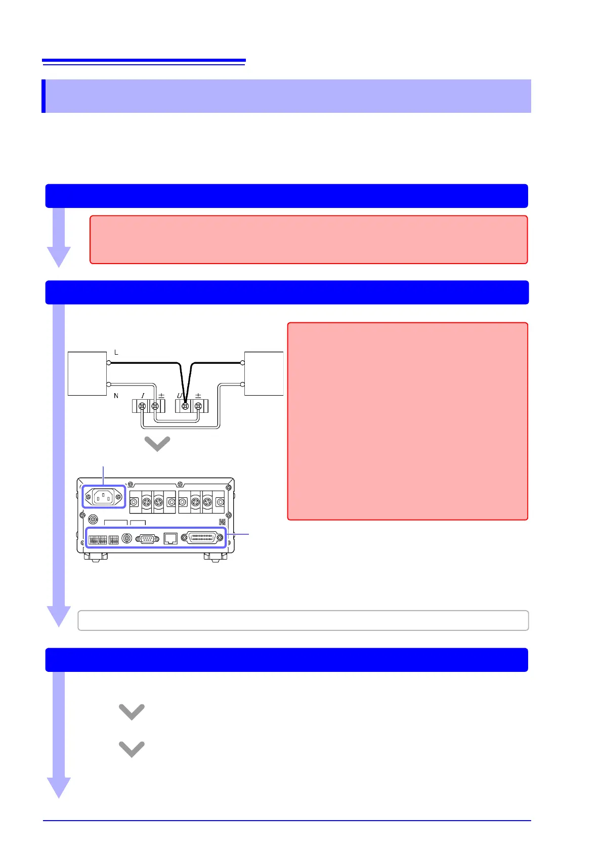
Connecting Wires and the Power Cord
Connect the measurement lines to the instrument and then connect the power cord to the instrument.
CHECKS
• Is the instrument connected on the secondary side of
the circuit breaker?
• Does the circuit being used exceed 1,000 V?
• Does the voltage or current being measured exceed
1,000 V or 30 A, respectively?
If so, use VT and CT.
• Are appropriate types of wire being used to connect to
the voltage and current input terminals?
Use solderless terminals that cover wiring with insula-
tion. Moreover, use wire with adequate dielectric
strength and current capacity.
• Has the wiring been shorted?
• Are the input terminals loose?
• Have wires been connected properly?
Connect wires. (p.26)
Example:
Connect the power cord. (p.33)
When using one or more current sensors, see "3.8 Using a Current Sensor" (p.100).
Source Load
Turning on the instrument (p.34)
Before turning on the instrument, verify that the wires have been connected properly one more time.
After displaying the initial screen, the instrument will display input values under the current settings.
Allow the instrument to warm up for at least 30 minutes.
Perform zero-adjustment.
To fulfill the instrument’s accuracy specifications, be sure to perform zero-adjustment for the voltage
and current measured values.