3.2 Configuring Settings
52
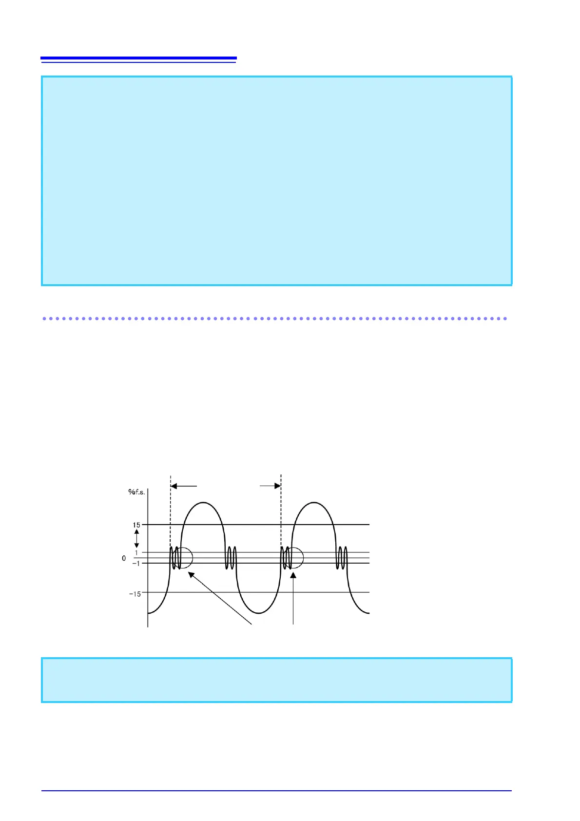
Significance of changing the zero-cross threshold level
The PW3335 calculates parameters such as RMS values and active power based on one cycle of the syn-
chronization source’s input waveform (voltage U or current I). This cycle is obtained by detecting the zero-
cross interval (the interval from one rising edge until the next cycle’s rising edge). Consequently, waveform
distortion due to a cause such as zero-cross noise near the rising edge of the input waveform set as the syn-
chronization source can cause detection of a zero-cross other than actual input waveform cycle, compromis-
ing the instrument’s ability to make accurate measurements. The PW3335 provides the function for setting a
threshold value used to judge zero-cross events caused by noise to be false, ignoring them. This threshold
value can be set in the range between 1% (default) and 15% of each measurement range, and is applied to
both the positive and negative sides. Once a zero-cross event is detected, the subsequent zero-cross events
will be ignored unless the input waveform goes across the upper or lower threshold value.
If zero-cross events are excessively detected due to input waveform distortion, the frequency is inaccuratly
measured. In that case, adjust the threshold level.
• When measuring an AC signal with a frequency lower than 500 Hz, it is recommended to set the fre-
quency measurement range (zero-cross filter) to 100 Hz or 500 Hz to reduce the noise component at 500
Hz and higher. Select the frequency measurement range depending on frequencies of signals to be mea-
sured.
• Frequency measurement accuracy is guaranteed for sine wave input that is at least 20% of the frequency
measurement source’s measurement range. The instrument may not be able to perform frequency mea-
surement accurately for other inputs (when the measurement signal is distorted, when there is a super-
posed noise component, etc.).
• The frequency measurement range cannot be changed while integration is being performed or during dis-
play hold or maximum value/minimum value hold operation.
• If a frequency of a signal to be measured is above the selected frequency measurement range, the instru-
ment may not be able to perform frequency measurement accurately. Change the frequency measure-
ment range to an appropriate one.
(Example) If a signal with a frequency above 500 Hz is input into the instrument with the frequency mea-
surement range that is set to 500 Hz, change the frequency measurement range to 5 kHz or
higher.
If the measurement of frequency is not performed accurately, neither does the correct detection of phase
shift between the voltage and current, the power factor or the reactive power are indicated inaccurately, and
the polarity of phase angle incorrectly.
Actual cycle
False cycle detection
Threshold level
setting range