3.2 Configuring Settings
40
This section describes how to select the information shown on the instrument’s display.
• Selecting display parameters
• Selecting rectifiers (p.42)
See: "Appendix 1 Detailed Specifications of Measurement Items (Display Items)" (p. A1)
Default settings
: Voltage (V), AC+DC
: Current (A), AC+DC
: Active power (W), AC+DC
: Power factor (PF), AC+DC
Selecting display parameters
This section describes how to select the parameters that are shown on the instrument’s display.
3.2.2 Selecting Display Content
• The voltage and current are displayed from 0.5% to 152% of the range.
(When input is less than 0.5% of the range, zero-suppression forces a value of zero to be displayed.)
• Active power is displayed from 0% to 231.04% of the range.
(There is no zero-suppression function.)
• Depending on the rectifier, certain display parameters cannot be measured. In this case, the display will
show [- - - - -].
See: "Appendix 1 Detailed Specifications of Measurement Items (Display Items)" (p. A1)
• The polarity symbol at the power factor indicates whether the current waveform lags or leads the voltage
waveform.
Symbol [None]: Current waveform lags voltage waveform
Symbol [-]: Current waveform leads voltage waveform
This symbol is linked to those at the reactive power and phase angle. However, if an input level of the volt-
age or current is 20% or less of the corresponding ranges, an incorrect polarity symbol may be displayed.
,
V → A → W → VA → var → PF → ° → VHz → AHz
→ Vpk → Apk → T.AV-A → T.AV-W → Ah+ → Ah-
→ Ah → Wh+ → Wh- → Wh → TIME →
TOTAL T.AV-A → TOTAL T.AV-W → TOTAL Ah+ →
TOTAL Ah- → TOTAL Ah → TOTAL Wh+ →
TOTAL Wh- → TOTAL Wh → TOTAL TIME → V ⋅⋅⋅
,
V → A → W → VA → var → PF → ° → RF-V % →
RF-A % → THD-V % → THD-A % → CF-V → CF-A
→ MCR → T.AV-A → T.AV-W → Ah → Wh → TIME
→ TOTAL T.AV-A → TOTAL T.AV- W → TOTAL Ah
→ TOTAL Wh → TOTAL TIME → V ⋅⋅⋅
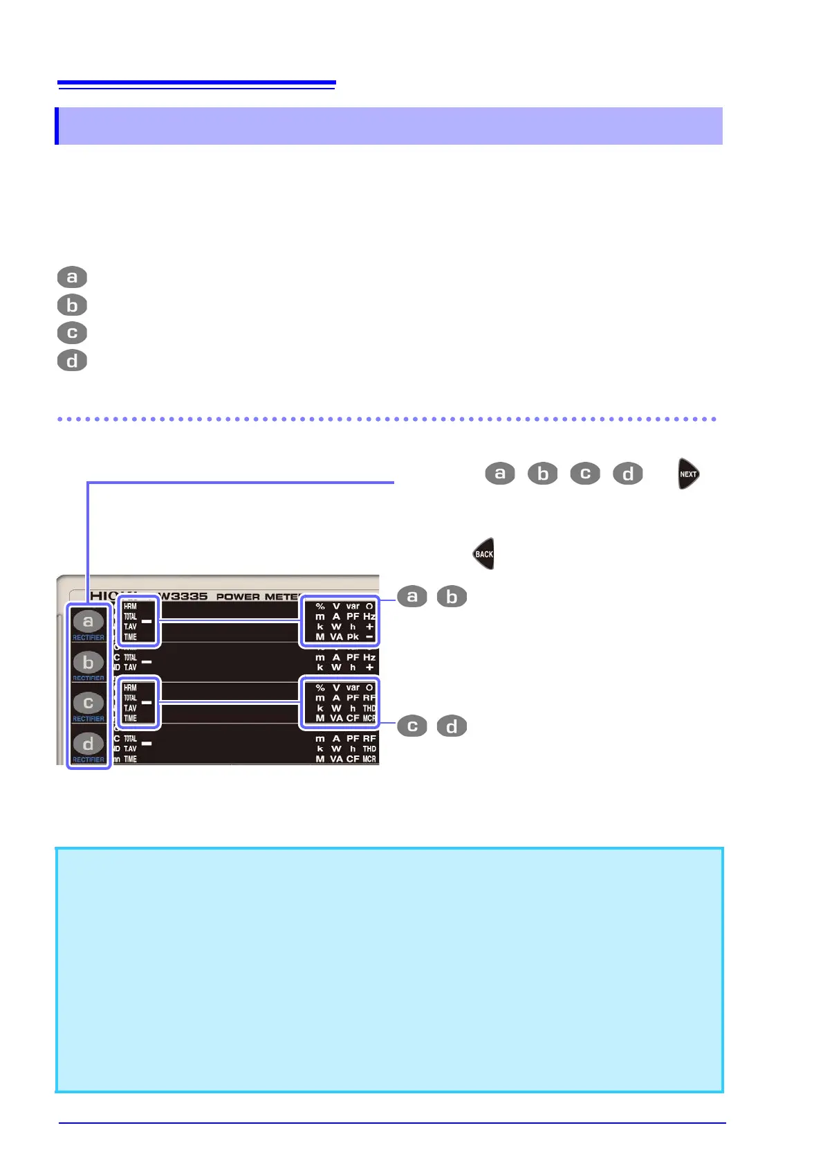
Every time , , , , or is
pressed, the each relevant display is
switched in the following order.
(Pressing will reverse the order.)