3.2 Configuring Settings
42
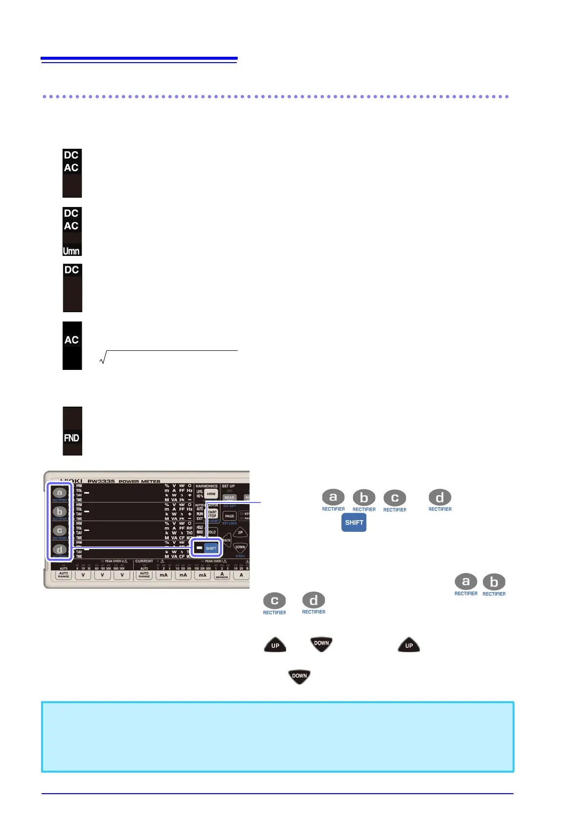
Selecting the rectifier
The instrument provides the five rectifiers listed below. Since data for all rectifiers is processed in parallel
internally, the rectifier can be switched during measurement.
Extracts and displays the fundamental wave component only using harmonic measurement.
5.
Displays calculated values given by the following equation as RMS values for the AC component
only for voltage and current:
The calculated value given by (active power AC+DC value) - (active power DC value) is displayed
as the active power value for the AC component only.
(AC+DC value)
2
- (DC value)
2
4.
Displays simple average values (DC components only) for voltage and current.
The calculated value (voltage DC value) × (current DC value) is displayed as the DC component
for active power.
3.
Displays true RMS values for DC only, AC only, or mixed DC and AC voltage and current.
1.
Displays mean value rectified RMS equivalents for DC only, AC only, or mixed DC and AC volt-
age. Current values are displayed as RMS values.
2.
Default setting: AC+DC
Every time , , , or is pressed
after pressing to activate the shift state,
the display will change as follows:
AC+DC → AC+DC Umn → DC→ AC → FND →
AC
+DC ⋅⋅⋅
The shift state is canceled approx. 2 seconds after , ,
, or is released.
You can also select the rectifier by pressing
or . (Pressing will reverse the
order.)
Use after canceling the shift state so that
zero-adjustment is not performed.
• When the DC rectifier is selected, the voltage (U) and current (I) polarity will also be displayed (as a sim-
ple average).
• When the AC+DC or AC rectifier is selected, the voltage and current display values will always be positive.
• Depending on the rectifier, certain display parameters cannot be measured. In this case, the display will
show [- - - - -].