3.6 External Control
84
Connecting wires to the external control terminals
Before connecting wires to the terminals, see "Connecting, Input and Measurement" (p.8).
Connect the wires to the terminals for the parameter you wish to control. Connect the GND terminal on the
instrument's external control terminals to the Lo (0 V) side of the contact signal or logic signal.
See: "External control terminals and description of control" (p.82)
Required item:
The external control terminals are input terminals for controlling the instrument by means of
either short/open contact signals or 0/5 V logic signals. Do not input a voltage in excess of
5 V.
To avoid an electrical accident, use the specified wire type.
1
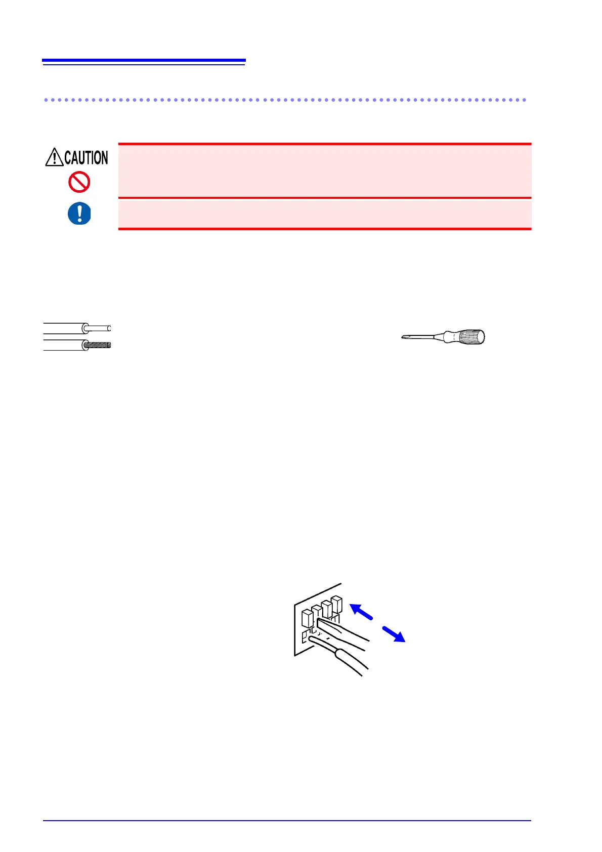
Press down on the button above each of the instrument’s external control terminals
using a tool, such as a flat head screwdriver.
2
While the button is depressed, insert the wire into the electric wire connection hole.
3
Wires
Recommended wires
Single strand diameter: φ 0.65 mm (AWG22)
Multi-strand: 0.32 mm
2
(AWG22)
Strand diameter: At least φ 0.12 mm or greater
Usable wires Single strand diameter: φ 0.32 mm to φ 0.65 mm (AWG28 to AWG22)
Multi-strand: 0.08 mm
2
to 0.32 mm
2
(AWG28 to AWG22)
Strand diameter: At least φ 0.12 mm or greater
Standard insulation stripping length 8 mm
Flathead screwdriver
Shaft diameter: φ 3 mm
tip width: 2.6 mm
Release the button.
The electric wire is locked in place.
To remove the wire:
Hold the button while pulling the wire out.
3
2
1