2.2 Connecting the Measurement Lines
27
Connecting the measurement lines
Please read "Handling the Instrument" (p.7) carefully before connecting the instru-
ment to the measurement lines.
Connect cables to the instrument’s voltage input terminals and current input terminals.
Safety covers
Observe the following to avoid electric shock and short circuits.
• The safety covers play a protective role by preventing contact with the terminals.
Always attach the safety covers before using the instrument.
• Turn off power to measurement lines before attaching or removing the safety cov-
ers.
• Verify that power to the measurement lines has been cut off before connecting the
instrument to them.
• To avoid electric shock or a short-circuit at the input terminals, use solderless termi-
nals that cover wiring with insulation.
• To prevent instrument damage or electric shock, use only the screws (M6×12 mm)
for securing the voltage input terminals and current input terminals in place and the
screws (M3×6 mm) for securing the safety cover in place that shipped with the prod-
uct. If you loose any screw or find that any screws are damaged, please contact your
Hioki distributor for a replacement.
• Use a Phillips head screwdriver with a No.3 tip. The screws’ tightening torque is 3 N•m.
• Use solderless terminals with a width of 13 mm or less.
• Tighten screws securely.
1
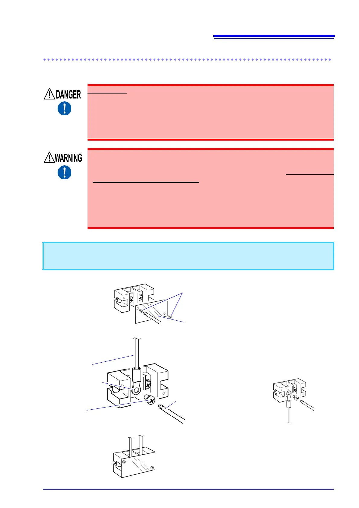
Remove the safety covers from the voltage input terminals and current input terminals.
2
Connect the cables to the voltage input terminals and current input terminals.
3
Attach the safety covers.
Remove the safety cover.
2
Remove the screws. (M3×6 mm)
1
Input terminal tight-
ening torque: 3 N
•m
1 Remove the screws with the Phillips head screwdriver
(No.3).
2 Position each wire as shown in the figure and secure in
place with the screw. (M6×12 mm)
Screw
(M6×12 mm)
Wire
Example: Voltage input terminal
Example: Current input terminal
Solderless terminal
(Width 13 mm or
less and capable of
accommodating an
M6 screw)
Phillips head screwdriver
(No.3)
Attach each cover securely. (screws: M3×6 mm)
 Loading...


