Connect the instrument to the measurement lines.
Source Load
Voltage input
terminal
Current input
terminal
When measuring measurement lines that are within the maximum input range
(voltage up to 1,000 V and current up to 30 A)
Connect the instrument to the measurement lines directly.
Instrument loss, which is caused by the input resistance of power measuring instruments’ volt-
age and current inputs, increases with the input voltage and input current as well as with certain
connection methods, and this in turn causes the error component of measured values to
increase. Consequently, it is necessary to consider instrument error as one cause of inaccu-
racy in the power measured values required by standards such as IEC 62301:2011 (Household
electrical appliance – Measurement of standby power). Calculate the instrument loss caused
by the PW3335 based on the procedure described in "Example instrument loss calculation and
connection method selection" (p.30) and choose the connection method that yields the least
instrument loss.
1
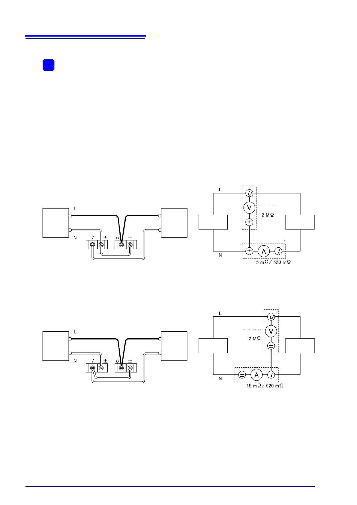
Method 1: Connect the current input terminals to the load side.
Wiring diagrams
Source Load Source Load
Voltage input
terminal
Input resistance
Current input
terminal
Method 2: Connect the voltage input terminals to the load side.
Wiring diagrams
Source Load
Input resistance
Input resistance
Input resistance