3.7 Using D/A Output
86
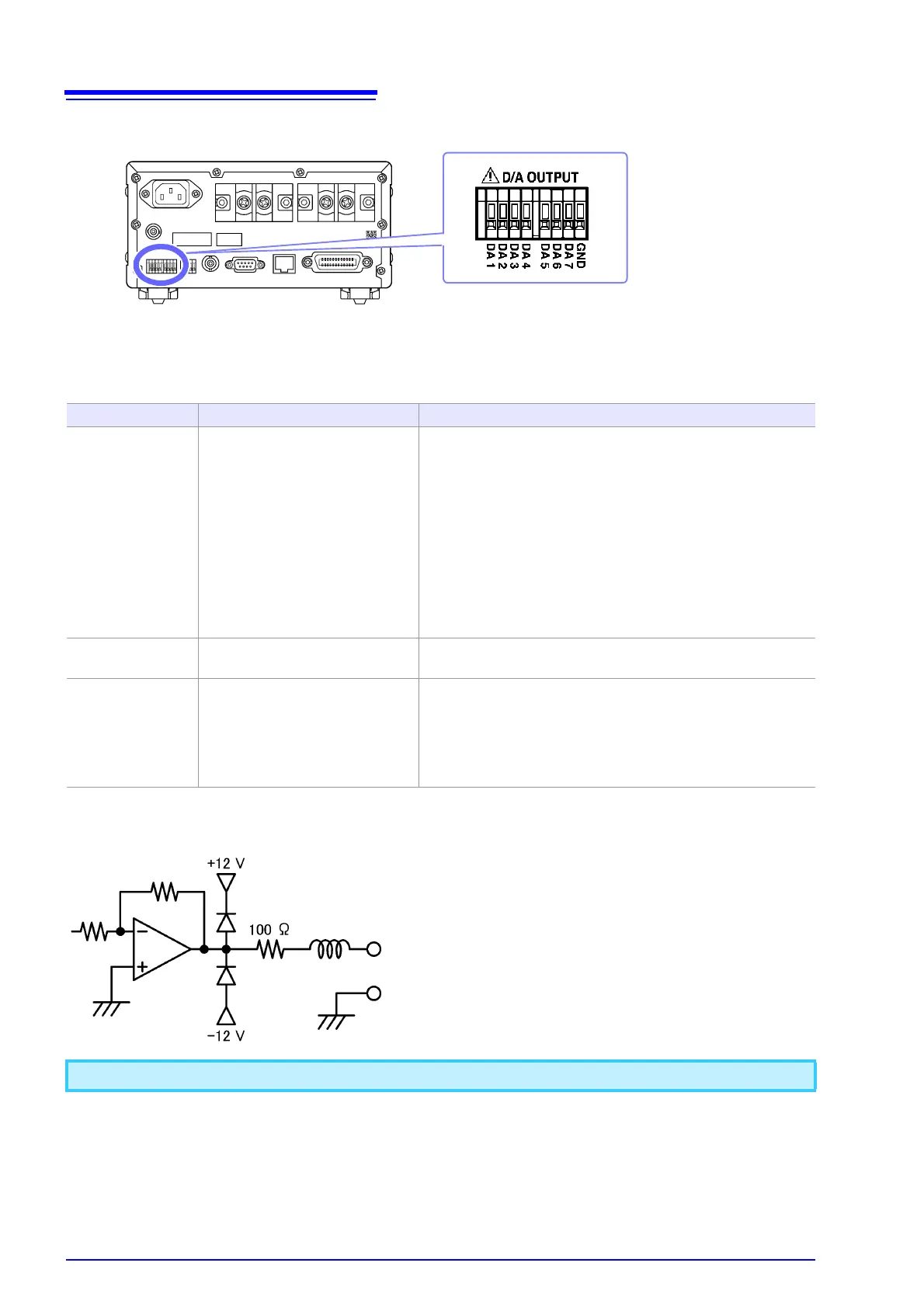
Output terminals and description of output
Available output parameters and output voltages (DA1 to DA7)
Output circuits
Output voltage Output parameters
Level output Select from
2 V (STD.2) and 5 V (STD.5).
Voltage (V), Current (A), Active power (W),
Apparent power (VA), Reactive power (var), Power factor (PF),
Phase angle ( ° ), Voltage frequency (V Hz),
Current frequency (A Hz), Time average current (T.AV A),
Time average active power (T.AV W),
Current integration (Ah, Ah+, Ah-),
Active power integration (Wh, Wh+, Wh-),
Voltage crest factor (CF V), Current crest factor (CF A),
Voltage ripple rate (RF V %), Current ripple rate (RF A %),
Total harmonic voltage distortion (THD V %),
Total harmonic current distortion (THD A %),
Maximum current ratio (MCR)
High-speed level
output
Select from
2 V (FASt.2) and 5 V (FASt.5)
Voltage (V), Current (A), Active power (W)
Waveform output 1 V (FASt)
Instantaneous voltage and instan-
taneous current
RMS level
Instantaneous power
Average level
Instantaneous voltage (V), Instantaneous Current (A),
Instantaneous power (W)
A maximum voltage of approximately ±12 V may be output from D/A output terminals.
Output terminal
The output impedance of each output termi-
nal is approximately 100 . When connecting
a recorder, DMM, or other instrument, use a
device with high input impedance (1 M or
greater).
 Loading...


