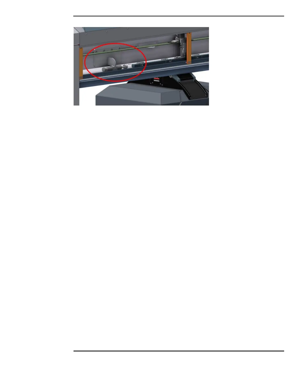
Fig. 31. Head Buffer Stop
The head buffer stop is employed to arrest the horizontal motion of the head in the event
that the scanner fails to stop at its configured software scan position limits.
The positions of the head buffer stops are factory-set to the required positions relative to
the end columns, and field adjustment is normally not required. The positions of these
head buffer stops are set in accordance with Machinery
Directive EN 349 to provide a minimum safe distance between the head and the inside of
the scanner frame. A minimum body crush gap of 500 mm (19.7 in) is required. For more
details and dimensions, refer to the specific installation drawings.
2.3.1.7 Motor Current Limit
Description:
The motor current limit (torque) is set at the factory on the motor controller, and confirmed
at installation.
Purpose:
Motor current is limited to ensure that the heads can be stopped manually with moderate
force, while still having enough torque for smooth scanning. This limits the potential harm
to an individual. If needed, authorized personnel can adjust the motor current limit.
2.3.1.8 Safety Warning Labels
Description:
See Table 6 for labels (without text), hazard descriptions, and placement locations on the
scanner. Labels are typically placed conspicuously at entry points to enclosures where
multiple hazards may exist, or in close proximity to hazard locations.
Purpose:
Safety labels have been placed on the scanner to highlight safety hazards to the user in
the general area.

 Loading...