220 HC900 Process & Safety Controller User and Installation Manual Revision 6
21 April 2017
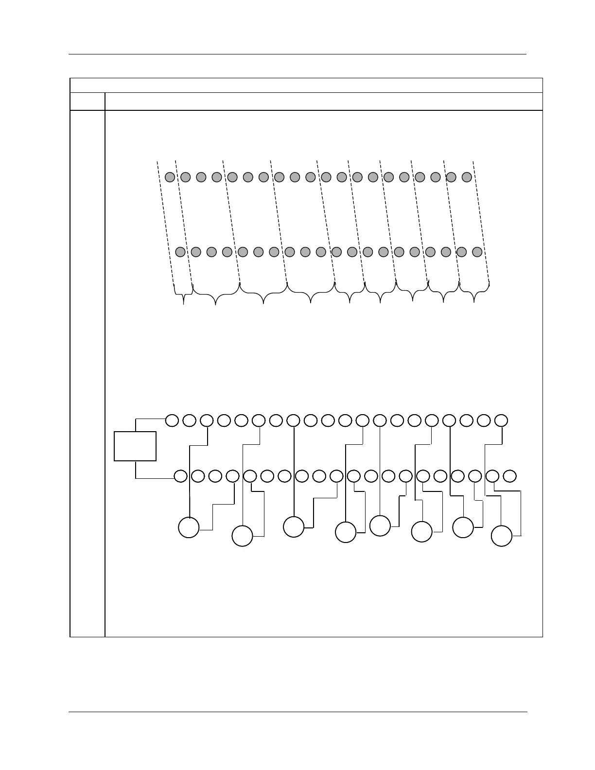
Connect field wiring.
Refer to Figure 97 through Figure 103 for field wiring. Any input type can be wired to any of the 8 inputs. After
wiring, double-check DIP switches settings for each input type (Step 3).
1 2 3 4 5 6 7 8 9 10 11 12 13 14 15 16 17 18 19 20
21 22 23 24 25 26 27 28 29 30 31 32 33 34 35 36 37 38 39 40
24V+
IN1+
IN5+
I
RTD5
I
RTD2
IN2+
I
RTD3
IN1+
I
RTD1
IN2+
IN3+
IN3+
I
RTD4
IN4+
I
RTD6
IN6+
IN7+
I
RTD7
I
RTD8
IN8+
24V
-
IN1
-
IN5
-
XMT5
XMT2
IN2
-
XMT3
IN1
-
XMT1
IN2
-
IN3
-
IN3
-
XMT4
IN4
-
XMT6
IN6
-
IN7
-
XMT7
XMT8
IN8
-
Input 1
Input 2
Input 3
Input 4
Input 5
Input 6
Input 7
Input 8
Use
SW9
power
switch
(Red 1/0)
Figure 97 – Analog input terminals
Transmitter Transmitter
1 2 3 7 8 94 5 6 10 11 12 13 17 18 1914 15 16 20
21 22 23 27 28 2924 25 26 30 31 32 33 37 38 3934 35 36 40
Transmitter
+
-
24 VDC
+
-
+
-
Transmitter
+
-
Transmitter
+
-
Transmitter
+
-
+
-
Input 1
Input 2
Input 3
Input 4
Input 5
Transmitter
Input 6
Transmitter
Input 7
-
+
Input 8
+
-
Note:
You must set
switches 1- 8 for
transmitters.
Transmitter Transmitter
1 2 3 7 8 94 5 6 10 11 12 13 17 18 1914 15 16 20
21 22 23 27 28 2924 25 26 30 31 32 33 37 38 3934 35 36 40
Transmitter
+
-
24 VDC
+
-
+
-
Transmitter
+
-
Transmitter
+
-
Transmitter
+
-
+
-
Input 1
Input 2
Input 3
Input 4
Input 5
Transmitter
Input 6
Transmitter
Input 7
-
+
Input 8
+
-
Transmitter Transmitter
1 2 3 7 8 94 5 6 10 11 12 13 17 18 1914 15 16 20
21 22 23 27 28 2924 25 26 30 31 32 33 37 38 3934 35 36 40
1 2 3 7 8 94 5 6 10 11 12 13 17 18 1914 15 16 20
21 22 23 27 28 2924 25 26 30 31 32 33 37 38 3934 35 36 40
Transmitter
+
-
24 VDC
+
-
+
-
Transmitter
+
-
Transmitter
+
-
Transmitter
+
-
+
-
Input 1
Input 2
Input 3
Input 4
Input 5
Transmitter
Input 6
Transmitter
Input 7
-
+
Input 8
+
-
Note:
You must set
switches 1- 8 for
transmitters.
Figure 98 – Two–wire transmitter connections with common 24 VDC supply

 Loading...


