389
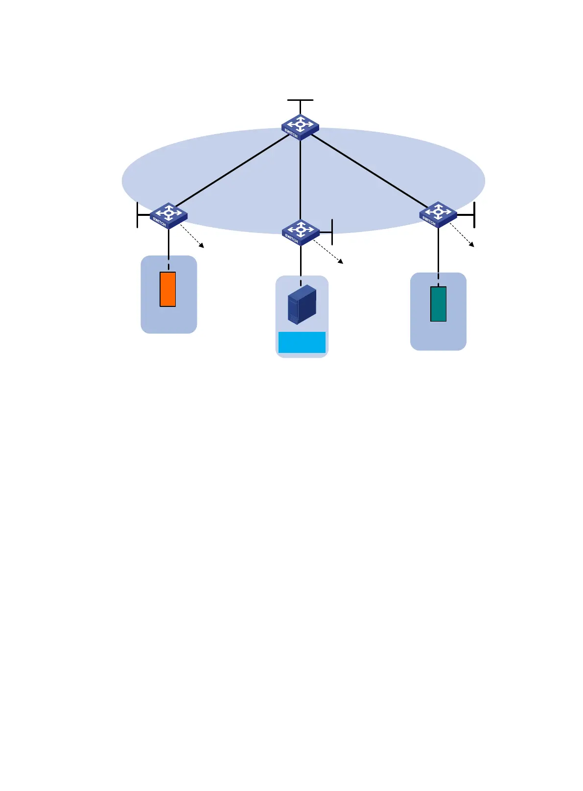
Figure 90 Network diagram
Configuration procedure
1. Configure IP addresses and subnet masks for interfaces, as shown in Figure 90. (Details not
shown.)
2. Configure Switch A:
# Enable L2VPN.
<SwitchA> system-view
[SwitchA] l2vpn enable
# Disable remote-MAC address learning and remote ARP learning.
[SwitchA] vxlan tunnel mac-learning disable
[SwitchA] vxlan tunnel arp-learning disable
# Create an EVPN instance in VSI instance view, and configure the system to automatically
generate an RT and RD.
[SwitchA] vsi vpna
[SwitchA-vsi-vpna] evpn encapsulation vxlan
[SwitchA-vsi-vpna-evpn-vxlan] route-distinguisher auto
[SwitchA-vsi-vpna-evpn-vxlan] vpn-target auto
[SwitchA-vsi-vpna-evpn-vxlan] quit
# Create VXLAN 10.
[SwitchA-vsi-vpna] vxlan 10
[SwitchA-vsi-vpna-vxlan-10] quit
[SwitchA-vsi-vpna] quit
# Configure BGP to advertise EVPN routes.
[SwitchA] bgp 200
[SwitchA-bgp-default] peer 4.4.4.4 as-number 200
Switch A
Switch B
Switch C
Switch D
IP transport
network
GE1/0/1
GE1/0/1
Vlan-int11
11.1.1.1/24
Vlan-int12
12.1.1.4/24
Loop0
1.1.1.1/32
Loop0
2.2.2.2/32
Loop0
4.4
.
4
.
4
/
32
Loop0
3.3.3.3/32
Vlan-int13
13.1.1.3/24
Vlan-int11
11.1.1.4/24
Vlan
-int13
13
.1.1.4/24
Vlan-int12
12.1.1.2/24
Service
node
1
VSI-int1
10.1.1.1/24
VSI-int1
10.1.1.1/24
VSI-int1
10.1.1.1/24
10.1.1.10
Server 1
10.1.1.20
Server 2
10.1.1.11
/24
V
M
1
V
M
2
 Loading...


